
Manual


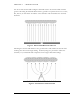
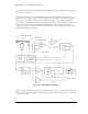

Table of Figures
Figure 1: Electric Field Mill at Ground Level
................................................... 3
Figure 2: Intensification of Electric Field
......................................................... 3
Figure 3: Field Mill Block Diagram
.................................................................. 4
Figure 4: EFM-100 Connection Diagram
......................................................... 5
Figure 5: A poor choice of mounting locations
................................................ 8
Figure 6: An excellent choice of mounting locations
....................................... 8
Figure 7: EPM-1 Power Module Connectors
.................................................... 9
Figure 8: EPM-1 Voltmeter Connections – Differential (Preferred
Connection)
...................................................................................................... 10
Figure 9: EPM-1 Voltmeter Connections – Single Ended
.............................. 10
Figure 10: EFA-10 Fiber Optic Adapter
.......................................................... 11
Figure 11: EFA-20 Fiber Optic Adapter
.......................................................... 11
Figure 12: Female Fiber Optic Connector
...................................................... 12
Figure 13: Male Fiber Optic Connector
.......................................................... 12
Figure 14: EFM-100 Field Mill Connections
................................................... 13
Figure 15: Sensitivity Plugs
............................................................................. 14
Figure 16: Correcting a Field Mill using a Reference Field Mill
.................... 15
Figure 17: Field Mill Grounding Detail
.......................................................... 17
Figure 18: EFM Options – General
................................................................. 19
Figure 19: EFM Options – High Field Alarm
................................................. 21
Figure 20: EFM Options – Very High Field Alarm
........................................ 22
Figure 21: EFM Options – Lightning Alarm
.................................................. 24
Figure 22: EFM Options - Delta Alarm
........................................................... 26
Figure 23: EFM Options – Data Logging
...................................................... 28
Figure 24: EFM Options – Data Sharing
........................................................ 29
Figure 25: EFM Options – Email & SMS Alerts
............................................ 30
Figure 26: Outgoing email server settings
....................................................... 31
Figure 27: SMS Modem Configuration
............................................................ 32
Figure 28: SMS Gateway Settings
.................................................................... 32
Figure 29: EFM-100 Software Display
............................................................ 33
Figure 30: Approaching Thundercloud
.......................................................... 35
Figure 31: Increasing Field due to Approaching Thundercloud
.................... 35
Figure 32: Thundercloud Directly Overhead
.................................................. 36
Figure 33: Electric Field Polarity Reversal
..................................................... 36
Figure 34: Departing Thundercloud
............................................................... 37
Figure 35: End of Storm Oscillation
............................................................... 37
Figure 36:
Step Changes in Field Magnitude Indicate Lightning
.................. 38
Figure 37: Precipitation Noise
........................................................................ 38
Figure 38: Field Mill Cleaning
......................................................................... 39