INDUSTRY PROCESS AND AUTOMATION SOLUTIONS Expansion Module EM-RES-02 Frequency Inverter 230 V / 400 V ACTIVE and ACTIVE Cube GB
General points on the documentation The present supplement of the documentation is valid for the frequency inverter series ACT and ACU. The information necessary for the assembly and application of the EM-RES-02 expansion module is documented in this guidance. For better clarity, the user documentation is structured according to the customerspecific demands made of the frequency inverter.
TABLE OF CONTENTS 1 General safety and application information .................................................................. 3 1.1 General information................................................................................................. 3 1.2 Proper use................................................................................................................ 3 1.3 Transport and storage .............................................................................................
1 General safety and application information This documentation has been created with greatest care and has been extensively and repeatedly checked. For reasons of clarity, we have not been able to take all detailed information on all the types of the products and also not every imaginable case of positioning, operation or maintenance into account.
1.3 Transport and storage Transport and storage are to be done appropriate in the original packing. Store the units only in dry rooms, which are protected against dust and moisture and are subjected to little temperature deviations only. Observe the climatic conditions according to standard EN 50178 and to the information on the label of the original packing. The duration of storage without connection to the admissible reference voltage may not exceed one year. 1.
2 Introduction This document describes the possibilities and the properties of the EM-RES-02 expansion module for the frequency inverters of the ACT and ACU device series. Note: This document exclusively describes the EM-RES-02 expansion module. It is not to be understood as fundamental information for the operation of the frequency inverters of the ACT and ACU device series. The EM-RES-02 expansion module is an optional hardware component to extend the functionality of the frequency inverter.
3 Installation of the EM-RES-02 expansion module 3.1 General The mechanical and electrical installation of the EM-RES-02 expansion module is to be carried out by qualified personnel according to the general and regional safety and installation directives. Safe operation of the frequency inverter requires that the documentation and the device specification be complied with during installation and start of operation.
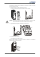
The EM-RES-02 expansion module is supplied in a housing for assembly on the lower slot of the frequency inverter. • Remove the lower cover (1) of the frequency inverter. The slot for the EM-RES-02 expansion module becomes accessible. 1 Caution! • The EM-RES-02 expansion module (2) is pre-fitted in a housing. Do NOT touch the PCB visible on the back, as modules may be damaged. Plug the EM-RES-02 expansion module (2) onto the slot (3). 2 3 • Re-install the lower cover (1).
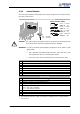
3.3 Danger! Electrical installation If the following instructions are not complied with, there is direct danger with the possible consequences of death or severe injury by electrical current. Further, failure to comply can lead to destruction of the frequency inverter and/or of the expansion module. • Before electrical installation of the EM-RES-02 expansion module, the frequency inverter must be de-energized. Take appropriate measures to make sure it is not energized unintentionally.
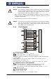
3.3.2 Control Sockets The control and software functionality can be freely configured for economical operation with a safe function. Expansion module EM-RES-02 Wieland DST85 / RM3,5 0.14 … 1.5 mm2 AWG 30 … 16 0.14 … 1.5 mm2 AWG 30 … 16 0.25 … 1.0 mm2 AWG 22 … 18 2 0.25 … 0.75 mm AWG 22 … 20 0.2 … 0.3 Nm 1.8 … 2.7 lb-in Caution! The control inputs and outputs must be connected and disconnected free of electrical power. Otherwise components may be damaged.
4 Control inputs and outputs 4.1 Analog input EM-S1INA 4.1.1 General The analog input of the EM-RES-02 expansion module can optionally be configured as a voltage or a current input.
4.1.3 Characteristic The mapping of the analog input signals onto a frequency or percentage reference value is possible for various demands. The parameterization is to be done via two points of the linear characteristic of the reference channel. The characteristic point 1, with the coordinates X1 and Y1, and the characteristic point 2, with the coordinates X2 and Y2, can be set in four parameters.
4.1.4.1 Examples The analog input signal is mapped onto a reference value as a function of the characteristic. The following examples show the operation modes for an analog voltage signal. The parameter Minimum Frequency 418 is set to the value 0.00 Hz. The characteristic point 100% for the Y-axis corresponds to the parameter Maximum Frequency 419 of 50.00 Hz in the examples. Attention! The various operation modes change the input characteristic as a function of the parameterized characteristic points.
Y 42.50Hz Characteristic point 1: X1 = 30.00 % · 10 V = 3.00 V (X2=80% / Y2=85%) Y1 = -50.00 % · 50.00 Hz = -25.00 Hz X 3.00V Characteristic point 2: X2 = 80.00 % · 10 V = 8.00 V Y2 = 85.00 % · 50.00 Hz = 42.50 Hz Tolerance band: ΔX = 2.00 % · 10 V = 0.20 V 8.00V -25.00Hz (X1=30% / Y1=-50%) The change of direction of rotation is done in the example at an analog input signal of 4.85 V, with a tolerance band of ±0.20 V.
Operation mode "101 – bipolar absolute value" The operation mode "101 – bipolar absolute value“ maps the bipolar analog signal onto a unipolar input characteristic. The formation of the absolute amount takes the characteristic into account comparable to the "bipolar" operation mode, but the characteristic points are reflected on the X-axis with a negative value for the Y-axis. Y 42.50Hz Characteristic point 1: X1 = -70.00% · 10 V = -7.00 V (X2=80% / Y2=85%) Y1 = -50.00% · 50.00 Hz = -25.00 Hz 25.
4.1.6 Tolerance band and hysteresis The analog input characteristic with change of sign of the reference value can be adapted by the parameter Tolerance band 560 of the application. The tolerance band to be defined extends the zero crossing of the speed relative to the analog control signal. The percentage parameter value is relative to the maximum current or voltage signal. Parameter No. Description 560 Tolerance band Min. 0.00 % Setting Max. 25.00 % (X2 / Y2) Fact. sett. 2.00 % (X2 / Y2) pos. max.
4.1.7 Error and warning behavior The monitoring of the analog input signal necessary according to the application is to be configured via the parameter Error/Warning behavior 563. Operation mode 0 - Off 1 - Warning < 1 V / 2 mA 2 - Shutdown < 1 V / 2 mA 3- Fault switch-off < 1 V / 2 mA Function The input signal is not monitored. If the input signal is less than 1 V or 2 mA, there is a warning message.
4.1.8 Adjustment As a result of component tolerances, it can be necessary to adjust the analog input. Parameter Adjustment 568 is used for this purpose. Operation mode 0 - no adjustment 1 - Adjustment 0 V / 0 mA 2 - Adjustment 10 V / 20 mA Function Normal operation Adjustment of the measurement with an analog signal of 0 V or 0 mA. Adjustment of the measurement with an analog signal of 10 V or 20 mA.
4.2 Resolver input EM-RES The resolver input is used for evaluating the position information from the resolver. The frequency of the field signal for the resolver can be selected via parameter Operation Mode 380. Operation mode 5- frequency 5 kHz 10- frequency 10 kHz 20- frequency 20 kHz Function Frequency of the reference signal for the resolver If the no. of resolver pole pairs > 1, the measured electric angle runs through the range of 0°...360° several times during one mechanical revolution.
• Set parameter Operation Mode 380 to the frequency value of the field signal for the resolver. • Adjust parameter No. of Pole Pairs 381 to the number of pole pairs of the resolver. Before adjusting the offset, take the following safety precautions: • Disable the frequency inverter via digital input S1IND (controller release). • If possible, uncouple the motor from the load so that the motor shaft turns freely. If installed, release the mechanical brake.
Depending on the behavior of the motor after start, carry out the following steps: − Motor does not turn, or the motor shaft only turns to a new position and stops again: • Check if the parameters No. of Pole Pairs 373 for the motor and No. of Pole Pairs 381 for the resolver are set correctly. If these values are adjusted correctly, take the following measures complying with the safety instructions.
4.2.2 Actual speed source Switch-over is effected via Actual Speed Source 766. If the resolver delivers the actual value signal for the speed controller, speed sensor 2 must be selected as the source In the basic setting, speed sensor 1 is used as the actual value source. Operation mode 1 - Speed sensor 1 2 - Speed sensor 2 4.3 Function The actual speed source is speed sensor 1 of the basic device (factory setting). The actual speed source is speed sensor 2 of the EMRES-02 expansion module.
4.4 Actual value display The actual value of speed sensor 2 can be read via the parameters Frequency speed sensor 2 219 and Speed, speed sensor 2 220. The analog input signal on analog input EM-S1INA can be a voltage or a current signal depending on the setting of switch S3. Accordingly, the actual value parameter Analog input EM-S1INA 253 is displayed as a percentage. 4.5 Repetition frequency output EM-RFOUT The repetition frequency output EM-RFOUT emulates a speed sensor.
5 Parameter list The parameter list is structured according to the menu branches of the control unit. For better clarity, the parameters are marked with pictograms: The parameter is available in the four data sets The parameter value is adjusted by the SETUP routine if a control method for a synchronous machine is selected for parameter Configuration 30. This parameter cannot be written in the operation of the frequency inverter 5.1 Actual value menu (VAL) Actual values of the machine No.
6 Annex 6.1 Error messages The various control functions and methods and the hardware of the frequency inverter contain functions which continuously monitor the application. As a supplement to the messages documented in these operating instructions, the following failure keys are activated by the EM-RES-02 expansion module. F14 21 22 23 24 Control connections Resolver synchronization not successful. Check resolver signal for interferences.
Bonfiglioli Worldwide & BEST Partners AUSTRALIA BONFIGLIOLI TRANSMISSION (Aust) Pty Ltd. 48-50 Adderley St. (East) Auburn (Sydney) N.S.W. 2144 Tel. (+61) 2 8748 4400 - Fax (+61) 2 9748 8740 P.o. Box 6705 Silverwater NSW 1811 www.bonfiglioli.com.au - bta1@bonfiglioli.com.au HUNGARY AGISYS AGITATORS & TRANSMISSIONS Ltd 2045 Törökbálint, Tö u.2. Hungary Tel. +36 23 50 11 50 - Fax +36 23 50 11 59 www.agisys.hu - info@agisys.com AUSTRIA MOLL MOTOR GmbH Industriestrasse 8 - 2000 Stockerau Tel.
INDUSTRY PROCESS AND AUTOMATION SOLUTIONS ACTIVE and ACTIVE Cube w w w. b o n f i g l i o l i . c o m COD.