
Operating instructions


08/06 9
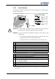
3.3.2 Control Sockets
The control and software functionality can be freely configured for economical opera-
tion with a safe function.
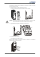
Expansion module EM-RES-02
0.14 … 1.5 mm
AWG 30 … 16
2
Wieland DST85 / RM3,5
0.14 … 1.5 mm
AWG 30 … 16
2
0.25 … 1.0 mm
AWG 22 … 18
2
0.25 … 0.75 mm
AWG 22 … 20
2
0.2 … 0.3 Nm
1.8 … 2.7 lb-in
Caution! The control inputs and outputs must be connected and disconnected free
of electrical power. Otherwise components may be damaged.
Attention! In order to minimize electromagnetic interference and to obtain a
g
ood
signal quality:
• Use a shielded, pair-twisted (SIN+ with SIN-, COS+ with COS-, both
field signal lines) cable for connecting the resolver.
• The line screen is to be connected to PE on a plane at both ends.
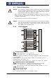
Socket X410A
Ter. Description
1 Resolver field signal EM-RES REF+
2 Resolver field signal EM-RES REF-
3 Resolver input EM-RES SIN-
4 Resolver input EM-RES SIN+
5 Resolver input EM-RES COS-
6 Resolver input EM-RES COS+
7 Repetition frequency output EM-RFOUT A+
1)
Socket X410B
Ter. Description
1 Repetition frequency output EM-RFOUT A-
-1)
2 Repetition frequency output EM-RFOUT B+
1)
3 Repetition frequency output EM-RFOUT B-
1)
4 Analog input EM-S1INA, resolution 12 bit,
U
max
= ±10 V (Ri = 100 kΩ),
I
max
= ±20 mA (Ri = 250 Ω)
5 Repetition frequency output EM-RFOUT R+
6 Repetition frequency output EM-RFOUT R-
7 Earth / GND
1)
The repetition frequency output is interference voltage proof in a range between
-5 V to +10 V.