
Operating instructions

08/06 13
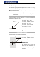
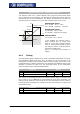
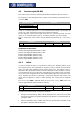
Characteristic point 1:
X1 = 30.00 % · 10 V = 3.00 V
Y1 = -50.00 % · 50.00 Hz = -25.00 Hz
Characteristic point 2:
X2 = 80.00 % · 10 V = 8.00 V
Y2 = 85.00 % · 50.00 Hz = 42.50 Hz
Tolerance band:
ΔX = 2.00 % · 10 V = 0.20 V
(X2=80% / Y2=85%)
8.00V
Y
X
-25.00Hz
42.50Hz
(X1=30% / Y1=-50%)
3.00V
T
he chan
g
e of direction of rotation is done
in the example at an analo
g
input si
g
nal o
f
4.85 V, with a tolerance band of ±0.20 V.
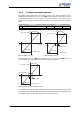
Operation mode "21 – unipolar 2…10 V / 4…20 mA"
This operation mode limits the input characteristic to the ran
g
e between 20% and
100% of the analog signal. If the value for a characteristic point of the X-axis is out-
side 0%, it is mapped to the characteristic point (2 V / 0 Hz).
The characteristic point on the X-axis is calculated according to the following formula:
20.00%20.00%)-(100.00%X valueparameter Xpoint sticcharacteri +
⋅
=
Characteristic point 1:
X1 = [-70.00% · (100.00% - 20.00%)
+ 20.00% ] · 10 V = -7.60 V
Y1 = -50.00% · 50.00 Hz = -25.00 Hz
Characteristic point 2:
X2 = [80.00% · (100.00% - 20.00%)
+ 20.00% ] · 10 V = 8.40 V
Y2 = 85.00% · 50.00 Hz = 42.50 Hz
Tolerance band:
ΔX = [2.00% · (100.00% - 20.00%)
· 10 V] = 0.16 V
(X2=80% / Y2=85%)
8.40V
Y
X
-25.00Hz
42.50Hz
(X1=-70% / Y1=-50%)
-7.60V
The characteristic point 1 has been dis-
placed to the point (2.00 V / 0.00 Hz). The
parameter
Tolerance band 560 is not
used in this example, as no chan
g
e of si
g
n
of the reference frequency value takes
place.
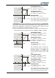
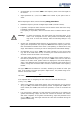
Characteristic point 1:
X1 = [30.00% · (100.00% - 20.00%)
+ 20.00% ] · 10 V = 4.40 V
Y1 = -50.00% · 50.00 Hz = -25.00 Hz
Characteristic point 2:
X2 = [80.00% · (100.00% - 20.00%)
+ 20.00% ] · 10 V = 8.40 V
Y2 = 85.00% · 50.00 Hz = 42.50 Hz
Tolerance band:
ΔX = [2.00% · (100.00% - 20.00%)
· 10 V] = 0.16 V
(X2=80% / Y2=85%)
8.40V
Y
X
-25.00Hz
42.50Hz
(X1=30% / Y1=-50%)
4.40V
T
he chan
g
e of direction of rotation is done
in the example at an analo
g
input si
g
nal o
f
5.88 V, with a tolerance band of ±0.16 V.