
Operating instructions

08/06 15
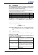
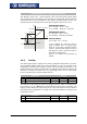
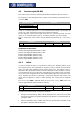
4.1.6 Tolerance band and hysteresis
T
he analo
g
input characteristic with chan
g
e of si
g
n of the reference value can be
adapted by the parameter
Tolerance band 560 of the application. The tolerance band
to be defined extends the zero crossin
g
of the speed relative to the analo
g
control
si
g
nal. The percenta
g
e parameter value is relative to the maximum current or volta
g
e
signal.
Parameter Setting
No. Description Min. Max. Fact. sett.
560 Tolerance band 0.00 % 25.00 % 2.00 %
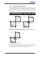
(X1
/
Y1)
-10V
(-20mA)
+10V
(+20mA)
(X2
/
Y2)
pos. max. value
neg. max. value
Without tolerance band
(
X
1
/
Y1)
-10V
(-20mA)
+10V
(X2
/
Y2)
pos. max. value
Tolerance band
neg. max. value
With tolerance band
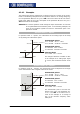
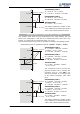
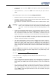
The
Minimum Frequency 418 or the Minimum reference percentage 518 set in the
factory extends the parameterized tolerance band to the hysteresis.
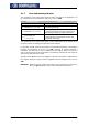
(X1
/
Y1)
(X2
/
Y2)
pos. max. value
pos. min. value
neg. min. value
neg. max. value
Tolerance band
With tolerance band and minimum value
For example, the output variable resulting from the positive input signals is kept at the
positive minimum value until the input si
g
nal is below the value for the tolerance band
in a negative direction. After that proceed on the set characteristic.