
Operating instructions

08/06 19
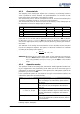
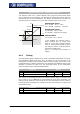
• Set parameter Operation Mode 380 to the frequency value of the field si
g
nal fo
r
the resolver.
• Adjust parameter No. of Pole Pairs 381 to the number of pole pairs of the re-
solver.
Before adjusting the offset, take the following safety precautions:
• Disable the frequency inverter via digital input S1IND (controller release).
• If possible, uncouple the motor from the load so that the motor shaft turns freely.
If installed, release the mechanical brake.
If uncoupling is not possible, make sure that the motor is loaded as little as possi-
ble.
Warning! In certain circumstances, the motor speed may reach hi
g
h values. If the
motor is not uncoupled from the load, personal and material dama
g
e
may result. To avoid such dama
g
e, make the followin
g
settin
g
s in any
case.
• Set the max. permissible output frequency of the frequency inverter to a low fre-
quency value via parameter
Switch-Off Limit 417. Select the frequency value such
that uncontrolled acceleration of the motor ("overspeedin
g
") is detected at an earl
y
stage. This limitation is necessary in order to avoid personal and material damage.
• Set parameter Current Limit 728 of the speed controller to a low current value
(e.
g
. 10% of the rated motor current). In this way it is made sure that there are no
excessive currents of the offset is set incorrectly.
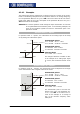
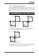
• Turn motor shaft manually. Check the sense of rotation of the resolver via the ac-
tual value of parameter
Frequency Speed Sensor 2 219. In the case of a clock-wise
rotation of the motor shaft, positive values are displayed for the actual frequency
value. If the displayed sense of rotation does not correspond to the actual sense o
f
rotation, change the connections SIN+ and SIN- at socket X410A of the frequenc
y
inverter.
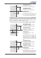
The Offset 382 must be between 0° and 360°, divided by the number of motor pole
pairs. If the number of resolver pole pairs is higher than 1, the possible range is be-
tween 0° and the max. offset.
number of motor pole pairs / number of resolver pole pairs
360
Offset Max.
°
=
If the adjusted value is changed by the max. offset, this does not affect the flux-
f
orming voltage 235.
• Adjust a low reference speed value (approx. 10% lower than the Switch-off Limi
t
Frequency 417), and enable the frequency inverter via digital input S1IND (con-
troller release) and S2IND (start clock-wise operation) in order to accelerate the
motor.
• If an overcurrent is detected or a fault messa
g
e is issued due to an overload, the
g
uided commissionin
g
(setup) will start first. Confirm the machine and resolve
r
data. After completion of the guided commissioning, adjust the parameter Limi
t
Current 728 to a low value a
g
ain because this value was overwritten durin
g
the
guided commissioning.