THE APPLIANCE IS FOR USE WITH NATURAL GAS OR L.P.G.
CONTACT INFORMATION INSTALLATION & SERVICING INSTRUCTIONS WORCESTER: PLEASE READ THESE INSTRUCTIONS CAREFULLY BEFORE STARTING INSTALLATION. TECHNICAL: 08705 266241 SERVICE: 08457 256206 SPARES: 01905 752571 LITERATURE: 01905 752556 TRAINING: 01905 752526 SALES: 01905 752640 WEBSITE: www.worcester-bosch.co.uk THESE INSTRUCTIONS ARE APPLICABLE TO THE WORCESTER APPLIANCE MODEL(S) STATED ON THE FRONT COVER OF THIS MANUAL ONLY AND MUST NOT BE USED WITH ANY OTHER MAKE OR MODEL OF APPLIANCE.
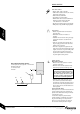
SAFETY & REGULATIONS CONTENTS SAFETY PRECAUTIONS & SYMBOLS 3 INSTALLATION REGULATIONS 3 APPLIANCE INFORMATION SAFETY & REGULATIONS APPLIANCE INFORMATION GENERAL INFORMATION 4 TECHNICAL DATA 5 LAYOUT & COMPONENTS 6-7 PRE-INSTALLATION 9 WATER SYSTEMS & PIPEWORK 10 CONDENSATE PIPEWORK 11 PRESSURE RELIEF PIPEWORK BOILER LOCATION & CLEARANCES PLUMBING MANIFOLD 12 13-14 15 FLUE TERMINAL POSITIONS 16 FLUE OPTIONS 17 INSTALLATION MAINS SUPPLY 8 PRE INSTALLATION CLEANING PRIMARY SYSTEMS
SAFETY & REGULATIONS SAFETY PRECAUTIONS INSTALLATION REGULATIONS IF YOU SMELL GAS: Gas Safety (Installation & Use) Regulations 1998: All gas appliances must be installed by a competent person in accordance with the above regulations. Failure to install appliances correctly could lead to prosecution.
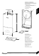
GENERAL INFORMATION STANDARD PACKAGE: A - Wall hung gas fired condensing combi boiler for central heating and domestic hot water B - Boiler support frame C - Hardware literature pack (When fitted to wall frame) Depth to wall 330mm B A APPLIANCE INFORMATION D - Bottom Panel 700mm D C SPECIFICATIONS: 400mm Pre-wired and pre-plumbed Galvanised steel inner frame Digital control system Automatic ignition Direct burner ignition electrodes D Built-in frost thermostat Built-in fault finding diagnostics
TECHNICAL DATA DESCRIPTION Domestic Hot Water UNITS NATURAL GAS 24i junior 28i junior L.P.G. 24i junior 28i junior Min. heat input KW 7.38 7.38 9.64 9.64 Max. rated heat output KW 24 28 24 28 Max. rated heat input KW 24.49 28.57 24.49 28.57 Natural Gas G20 m3/h 2.59 3.02 - - Propane Gas (LPG) kg/h - - 1.9 2.22 Max. mains inlet pressure bar 10 10 10 10 Min. mains inlet pressure (working) for max flow bar 1.3 1.3 1.3 1.3 Min.
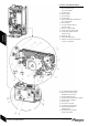
LAYOUT & COMPONENTS 1 2 3 4 5 6 7 8 9 10 11 12 13 14 15 16 17 18 19 20 21 22 23 24 25 26 27 28 29 30 31 32 33 34 35 36 AIR / GAS MANIFOLD FAN AIR / GAS ADJUSTMENT SCREW GAS VALVE INLET PRESSURE TEST POINT EXPANSION VESSEL WALL MOUNTING FRAME COVER FOR EXTERNAL WIRING CONNECTIONS CONDENSATE CONNECTION FROM HEAT EXCHANGER PLATE TO PLATE DHW HEAT EXCHANGER FLUE PRESSURE SWITCH FAN PRESSURE TEST POINT MANUAL VENT POINT IGNITION AND FLAME SENSE ELECTRODES OVERHEAT THERMOSTAT FLAME VIEWING MIRROR SECURING NUT,
LAYOUT & COMPONENTS APPLIANCE INFORMATION 10 PLATE TO PLATE DHW HEAT EXCHANGER 32 SYSTEM PUMP 36 FLOW TURBINE 37 UNUSED PORT 38 AUTO AIR VENT 39 FLOW CONNECTION FROM BOILER HEAT EXCHANGER 40 DHW SENSOR 41 CH FLOW CONNECTION TO SERVICE VALVE 42 DHW OUT CONNECTION 43 COLD WATER IN CONNECTION 44 CH RETURN CONNECTION TO SERVICE VALVE 45 DIVERTER VALVE 46 PRESSURE RELIEF VALVE 47 COMPACT HYDRAULIC MOUNTING SCREW (2) TO BOILER 48 CH TEMPERATURE CONTROL 49 MAINS ON/OFF INDICATOR/ DIAGNOSTIC LIGHT (BLUE) 50 SERV
CLEANING PRIMARY SYSTEMS IMPORTANT: All the following Pre-Installation sections must be read and requirements met before starting boiler or flue installation. CAUTION: ISOLATE THE MAINS SUPPLIES BEFORE STARTING ANY WORK AND OBSERVE ALL RELEVANT SAFETY PRECAUTIONS. IMPORTANT: Debris from the system can damage the boiler and reduce efficiency. Failure to comply with the guidelines for t he use of wat er treatment with the appliance will invalidate the appliance warranty.
MAINS SUPPLY ELECTRIC SUPPLY: • Supply: 230V - 50Hz, 140 watts • Cable: PVC insulated 0.75mm2 (24 x 0.2mm) temperature rated to 90°C. • External 3A fuse to BS1362. • The appliance must be earthed. • IPX4D. NOTE: this is reduced to IP20 if the following mechanical timers are fitted: 7 716 192 036 or 7 716 192 037. • All pipes to the boiler must be cross-bonded. • Wiring must comply with IEE wiring regulations. PRE INSTALLATION GAS SUPPLY: • Boilers using NG must be connected to a governed meter.
WATER SYSTEMS & PIPEWORK SYSTEM FILL TYPICAL SEALED SYSTEM A - Appliance expansion vessel central heating B - Extra expansion vessel central heating return C - Drain cock P - Pressure relief discharge R - Radiators PRE INSTALLATION PRIMARY SYSTEMS CONNECTIONS/VALVES: • All system connections, taps and mixing valves must be capable of sustaining a pressure up to 3 bar. • Radiator valves should conform to BS2767:10. • All other valves should conform to BS1010.
CONDENSATE PIPEWORK PRE INSTALLATION CONDENSATE PIPEWORK: • The condensate pipe must be a minimum of 22mmØ plastic pipe. • The condensate pipework must fall at least 50mm per metre towards the outlet and should take the shortest practicable route. • The pipework must follow one of the options shown opposite into an internal serviceable trap (min. 75mm) such as a sink/washing machine) or discharge direct into a vent stack (E) 450mm min.
PRESSURE RELIEF PIPEWORK PRESSURE RELIEF PIPEWORK: IMPORTANT: The pressure relief valve is a safety device for the boiler and if activated may discharge boiling water steam through the relief valve drain pipe. • The pressure relief drain pipe (M) from the boiler should be at least 15mm diameter copper pipe and run downwards away from any electrics or other hazard, preferably to an external drain or soakaway.
SERVICING CLEARANCES VENTED COMPARTMENT BOILER LOCATION & CLEARANCES This boiler is only suitable for installing internally within a property at a suitable location onto a fixed, rigid non-combustible surface at least the same size as the boiler and capable of supporting the boiler weight. COMPARTMENTS: Follow the requirements of B S6798 and BS5440 Part 2 and note: • Minimum clearances must be maintained • An access door is required to install, service and maintain the boiler and any ancilliary equipment.
BOILER LOCATION & CLEARANCES 1 1 2 2 3 Otherwise the appliance can be fitted in both zones 2 and 3 . See IEE wiring regulations. I M PORTANT: any switch or appliance control using mains electricity must not be able to be touched by a person using the bath or shower. Electrical switches, fused spur and socket out let s must not be sit uat ed in t he bathroom.
PLUMBING MANIFOLD Gas Supply (alternative from above appliance) 22mm CH Flow 22mm DHW OUT 15mm DHW IN (alternative from above appliance) 15mm CH Return 22mm CONNECTIONS: Heating System: 22mm compression fittings DHW: 15mm compression fittings Gas: 22mm compression fittings Use the fittings supplied in the Lit/Hardware pack. • If the boiler pipes are to be run behind the appliance ensure that the pipes pass through the slot in the yellow plastic guide (A). This is fitted to the boiler frame.
Minimum dimensions of flue terminal positions for balanced room sealed flues with fanned draught: DRWG. REF: TERMINAL POSITION DISTANCE A1 Directly below an opening, air brick, opening windows, etc. 300mm B1 Above an opening, air brick, opening window, etc. 300 mm Horizontally to an opening, air brick, opening window, etc.
FLUE OPTIONS STANDARD FLUE HORIZONTAL MAXIMUM FLUE VERTICAL START + 2 BENDS A A F B C Ø100 MAX 686 A x 1 MIN 250 A x 1* Ø100 - 2600mm Ax1+Cx2+ Bx4 + Fx1 Ø125 MAX 1070 A x 1 MIN 250 A x 1* * Requires cutting Ø125 - 11000mm A x 1 + C x 2 + B x 13 + Fx1 PRE INSTALLATION MAXIMUM FLUE HORIZONTAL MAXIMUM FLUE VERTICAL START + 3 BENDS • The diagrams (opposite) show the components used and the maximum flue length for each configuration of 100mm and 125mm flues.
UNPACKING WALL FRAME AND IIMPORTANT: All the previous Pre-Installation sections must be read and requirements met before starting boiler or flue installation. ANCILLARY ITEMS LIFTING AND CARRYING PRECAUTIONS: • Lift only a manageable weight, or ask for help. • When lifting or putting things down, bend the knees, and keep the back straight and feet apart. • Do not lift and twist at the same time.
A WALL MOUNTING TEMPLATE FLUE OPENING X4 CAUTION: Ensure there are no pipes, electric cables, damp proof courses or other hazards before drilling. X4 SAFETY: All relevant safety precautions must be undertaken. Protective clothing, footwear, gloves and safety goggles must be worn as appropriate. USE APPROPRIATE FIXINGS FOR WEIGHT AND WALL TYPE FIXING THE MOUNTING FRAME: • The boiler template shows the relative positions of the flue and the top and bottom fixing of the mounting frame.
UNPACKING THE APPLIANCE UNPACKING THE APPLIANCE 4 A - Outer carton B - Inner sleeve (unwraps from front) 5 C - Packaging base D - Protective wrapping A E - Appliance outer case F B B C F C 6.1 E 6 6.2 H 4. Remove outer carton (A) and place safely away from the working area. 5. With the outer packaging removed and the inner sleeve (B) still in place gently lay the boiler on its back. 6. The boiler will lie at an angle to the floor to allow the boiler outer casing (E) to be removed.
Do not lift by the air gas manifold. 3 BOILER CONNECTIONS CAUTION: ISOLATE TH E MAI NS GAS SUPPLY BEFORE STARTING ANY WORK AND OBSERVE ALL RELEVANT SAFETY PRECAUTIONS. A GAS AND WATER CONNECTIONS: Remove template and secure the wall mounting frame to the wall with the fixings supplied. System pipes may be run vertically upwards behind the boiler or below it. See Plumbing Manifold Section on page 15.
BOILER CONNECTIONS 5 F CAUTION: ISOLATE TH E MAI NS GAS SUPPLY BEFORE STARTING ANY WORK AND OBSERVE ALL RELEVANT SAFETY PRECAUTIONS. GAS AND WATER CONNECTIONS: A - CH flow (22mm), B - CH return (22mm), C - Gas inlet (22mm), D - Mains water inlet A E B H 5. Lower the control panel into the service position by removing the screw (F) from the retaining bracket. 6. Make connections to the heating system. Connect the gas supply to the boiler gas cock 22mm compression.
FLUE INSTALLATION WALL 189mm 93mm HORIZONTAL FLUE (60/100mm diameter) For vertical flues and 80/125mm horizontal flues, please refer to separate instructions supplied with the flue kit. NOTE: to ease the assembly of flue components, apply silicone lubricant to sealing surfaces. The instructions for the 60/100mm diameter flue are shown below. MEASURING THE FLUE (Standard Flue): Measure from the outside wall to the centre line of the flue turret.
FLUE INSTALLATION Clamp MEASURING THE FLUE (Extension Flue Kits): ONLY CUT EXTENDED FLUE LENGTHS As with the Standard Flue measure from the outside wall to the centre line of the flue turret. Subtract the length of the Standard Flue and turret (725mm) from length L . Subtract the full length 1m extension(s) from the figure. Cut one of the 1m extensions to the remainder. Cut both tubes square taking care not to distort the tubes. Remove any burrs.
FLUE INSTALLATION A - Standard Flue B - Internal Wall Seal ASSEMBLING THE FLUE 1 Slide inner collar (B) onto terminal (A) 2 Additional extensions or bends: Push fit all extensions/bends/terminal together and secure connections with clamps (D). The slope of the terminal outlet must face downwards.
CONDENSATE CONNECTION CONDENSATE CONNECTION: Never terminate or discharge into any open source, including; sink, bath, shower, bidet, toilet etc. Note: any external condensate pipework should be protected with weather resistant insulation to help prevent freezing. • Ensure that the condensate drain is 22mm diameter plastic pipe. It must fall at least 50mm per metre towards the outlet. INSTALLATION • An adapter in 22mm pipe is contained in the fitting pack (A) along with sealing washer (B).
1 ELECTRICS 2 A CAUTION: ISOLATE THE MAINS ELECTRICITY SUPPLY BEFORE STARTING ANY WORK AND OBSERVE ALL RELEVANT SAFETY PRECAUTIONS B 3 C ROOMSTAT ONLY 4 Mains supply to the boiler must be through a fused double pole isolator situated adjacent to the appliance. The isolator must have a contact separation of 3mm minimum in all poles. External fuse rating 3A. When stripping wires always ensure copper strands do not fall into the control box.
POSITION OF WIRED COMMISSIONING INSTALLATION COMPONENTS 28 INSTALLATION & SERVICING INSTRUCTIONS FOR WORCESTER GREENSTAR 24 i junior/28 i junior 8 716 107 336b (11/05) POSITION OF WIRED COMPONENTS
PRE-COMMISSIONING 1 A D B CHECKS CAUTION: ISOLATE THE MAINS SUPPLIES BEFORE STARTING ANY WORK AND OBSERVE ALL RELEVANT SAFETY PRECAUTIONS 1 Check that the service and water pipes are connected to the correct position on the manifold. A - CH Flow (22mm) B - CH Return (22mm) C - Gas inlet (22mm) D - DHW (15mm) E - Water in (15mm) 2 Check the gas type specified on the identification plate (F) matches that of the gas supply.
FILLING THE SYSTEM 2 3 4 E C D 5 A • • B Turn on the water main and open the system valves. Open all radiator valves. Fill the system via a WRAS approved filling loop to 1 bar then turn the valve anti-clockwise to close. Vent (A) any air from the boiler heat exchanger using a suitable container to collect any water. Ensure tube outlet (B) is directed away from the fan or any other electrical component to prevent any water damage.
STARTING THE APPLIANCE IMPORTANT: Never run the appliance when the appliance/system is empty or partially filled.
1 A WATER TREATMENT 5 IMPORTANT: Debris from the system can damage the boiler and reduce efficiency. Failure to comply with the guidelines for t he use of wat er treatment with the appliance will invalidate the appliance warranty. J B K ENSURE THAT THE SYSTEM HAS BEEN CLE AN E D AS ON PAG E 8 OF TH E S E INSTRUCTIONS.
COMMISSIONING NOTE: When running in the service mode, the boiler will operate both the central heating and the domestic hot water circuits. This is to allow sufficient time for this part of the commissioning procedure. It will be necessary to run water through the domestic hot water circuit to ensure that the boiler will not cycle on low heating demands. I COMMISSIONING A H D E F G THE COMBUSTION FOR THE APPLIANCE IS FACTORY SET. NO ADJUSTMENT IS REQUIRED IF THE GAS INLET PRESSURE IS CORRECT.
FINISHING COMMISSIONING The boiler has been factory set, so there should be no need to adjust any controls. REPLACE OUTER CASING: 1 Replace outer casing making sure that the securing points are properly located. Replace top two screws (A). Retighten bottom two screws (B). A INSTALLING BOTTOM PANEL: 2 The bottom panel slides onto two ledges (C) either side of the boiler frame. Hold the panel up against the underside of the boiler and slide towards the rear until it is fully engaged.
INSPECTION AND SERVICE CAUTION: TURN OFF THE GAS SUPPLY AND ISOLATE THE MAINS S U P P LI E S B E FOR E STARTI NG ANY WOR K AN D OB S E RVE ALL RELEVANT SAFETY PRECAUTIONS. I M P ORTANT: Any service work must be carried out by competent registered engineers such as British Gas or Corgi registered personnel. IMPORTANT: AFTER REPLACEMENT OF ANY COMPONENTS ALWAYS CHECK FOR GAS SOUNDNESS WHERE RELEVANT AND CARRY OUT FUNCTIONAL CHECKS AS DESCRIBED IN COMMISSIONING.
1. 1.2 INSPECTION AND SERVICE 1.1 Component Access 1. Removing outer case A 1. B 1.3 Remove bottom panel by pulling it forward and off. 1.1 Undo and remove 2 screws (A) securing boiler casing at the top of the appliance. 1.2 Undo but do not remove the 2 screws (B) securing boiler casing at the bottom of the appliance. 1.3 Pull case forward and remove. 2. Adjusting boiler control to service position 2.1 2.1 Remove screw (C) securing control. 2.
INSPECTION AND SERVICE Setting Boiler to Maximum. NOTE: When running in the service mode, the boiler will operate both the Central Heating and DHW circuits. This is to allow sufficient time for the setting procedure. It will be necessary to run water through the DHW circuit to ensure that the boiler will not cycle on low heating demands.
INSPECTION AND SERVICE COMBUSTION TESTING MUST BE CARRIED OUT BY A COM PETE NT PE R SON. IT M UST NOT BE ATTEMPTED UNLESS THE PERSON CARRYING OUT THE COMBUSTION CHECK I S E Q U I P P E D W ITH A C O M B U STI O N ANALYSER CONFORMING TO BS 7927 AND IS COMPETENT IN IT’S USE. I M P ORTANT: I F TH E JOI NT BETWEEN THE AIR/GAS MANIFOLD AN D TH E H EAT E XCHANG E R I S DISTURBED THE SEALING GASKET MUST BE REPLACED.
5 INSPECTION AND SERVICE E 4 5 6 7 8 6 F Remove electrical connector from fan. Undo and remove securing nut (E) from the top of the heat exchanger. Remove stainless steel viewing mirror (F). Rotate fan and air/gas manifold assembly (G) around the top of the heat exchanger until it stops at the lug. Lift up assembly and remove from boiler. Disconnect spark electrode and flame sensor connections (J). Remove clamping plate (K). Remove spark/flame electrode assembly from boiler.
INSPECTION AND SERVICE Q 9 Small tab 9 Remove burner (L). Remove top baffle (M). Remove baffle (N). Remove the two hexagon headed screws (O) retaining the access cover (P) on the sump. Access the heat exchanger flue ways by inserting the cleaning brush (7 716 192 312) through the top access hole in the casing (Q). Clean heat exchanger flue ways (R) using the cleaning brush (7 716 192 312) removing any debris from the access point in the sump.
REPLACEMENT OF PARTS CAUTION: TURN OFF THE GAS SUPPLY AND ISOLATE THE MAINS S U P P LI E S B E FOR E STARTI NG ANY WOR K AN D OB S E RVE ALL RELEVANT SAFETY PRECAUTIONS. 1. Removing outer case 1.1 Undo 4 screws (A) securing boiler casing. 1.2 Pull case forward and remove. To remove bottom tray, pull forward on the tag on the underside of the tray. IMPORTANT: AFTER REPLACEMENT OF ANY COMPONENTS ALWAYS CHECK FOR GAS SOUNDNESS WHERE RELEVANT AND CARRY OUT FUNCTIONAL CHECKS AS DESCRIBED IN COMMISSIONING.
5.1 REPLACEMENT OF PARTS 5.2 The following components require the control to be moved in to the service position: Gas valve Siphon PCB fuse Transformer A 5. Moving boiler control to service position 5.1 Remove screw (A) securing control. 5.2 Gently pull forward. 6. Gas valve 6.1 7 Isolate gas supply at boiler gas cock. 6.1 Remove wire clip from gas valve outlet then pull gas adjustment assembly free from plastic connector and pull forward clear of case. 6.
REPLACEMENT OF PARTS 9 9. Access to boiler control components Remove 3 screws (A) and remove cover from control. A 10. PCB fuse Remove fuse F1(B) from the PCB and replace. There is a spare fuse clipped into the underside of the electrical cover. 11.Transformer / PCB Disconnect all electrical connections from the control. Remove 5 screws (C) retaining the rear panel of the control and remove panel. 10 B SERVICING & SPARES Spare Fuse order T1.6L 250V F2 T2.
REPLACEMENT OF PARTS 12 A 12. Replacing control B 12.1 C C C 12.2 The control is supplied within its plastic housing. The complete unit must be replaced. Remove ALL electrical connections from the control PCB including where cables run through restraints. These can be unclipped from the plastic moulding noting their position. Remove the code plug (B). The code plug should be left attached to the frame of the boiler by its plastic safety thread. 12.
13.1 A REPLACEMENT OF PARTS The following components require the air / gas manifold and fan assembly to be removed: Pressure switch Fan Electrode assembly Burner Heat exchanger 13.2 B 13.3 I M P ORTANT: I F TH E JOI NT BETWEEN THE AIR/GAS MANIFOLD AN D TH E H EAT E XCHANG E R I S DISTURBED THE SEALING GASKET MUST BE REPLACED. IMPORTANT: AFTER REASSEMBLY TH E C OM B USTION M UST B E CH ECK E D US I NG TH E P RO CEDURE IN THE SECTION “SETTING THE GAS AIR RATIO”.
REPLACEMENT OF PARTS 15.1 15.2 15. Fan 15.1 Remove 3 screws (A) retaining mixing chamber. 15.2 Remove 2 screws (B) retaining the fan to the air/gas manifold. 15.3 Remove screw (C) retaining plate and remove. Re-assemble with new fan ensuring seals are correctly fitted. B A 16. Electrode assembly 15.3 16 C Disconnect spark electrodes and flame sensor connection. Remove clamping plate (D). Remove spark/flame electrode assembly (E) from heat exchanger. 17.
REPLACEMENT OF PARTS 19.1 A 19. Diverter valve motor Insure the appliance is in service mode (there is no need to drain the appliance). Disconnect the electrical connector from the diverter valve motor. 18.1 Pull the motor assembly (A) towards you. The assembly will slide free from the valve. To refit, follow the above in reverse. 20. Diverter valve 20.1 Ensure the appliance has been fully drained. Disconnect the electrical connector from the diverter valve motor.
A 23.1 REPLACEMENT OF PARTS 23.2 23. Pump head Ensure the boiler is fully drained (see draining the appliance). Disconnect the electrical connection from the bottom of the pump. 23.1 Remove the four Allen bolts (A) securing the pump at each corner. 23.2 Gently pull the pump towards you and remove. To refit, follow the above in reverse. A Pressure gauge 24.1 Ensure the appliance has been fully drained (see draining the appliance).
27.1 REPLACEMENT OF PARTS 27. Hydraulic Block 27.2 Ensure the appliance has been fully drained (see draining the appliance). Disconnect the electrical connections to the NTC, Turbine and pump. Undo the nuts securing the copper water pipes to the manifold (there is no need to remove the gas pipe) Release the spring clips securing these water pipes to the plastic housing and remove the pipes. Release the spring clip securing the expansion vessel pipe to the plastic housing and remove the pipe.
REPLACEMENT OF PARTS 29.1 29. Plastic protection device 29.2 A Ensure the system is fully drained (see draining the appliance). Disconnect all pipes connected to the pump housing. Remove the electrical connection to the pump. Withdraw the metal clip to the right of the pump head to release the pump housing. Slide the device to the left and then withdraw it from the appliance. 29.1 Remove the spring clip from the pressure relief valve housing. 29.2 Withdraw the pressure relief valve (A).
REPLACEMENT OF PARTS 31.1 31. Bypass valve 31.2 Remove the Hydraulic block from the boiler (See Removing the Hydraulic Block). 31.1 Remove the two spring clips at either end of the copper bypass pipe. Undo the screw securing the left hand plastic housing to the heat exchanger Move the housing to the left to free up the one end of the pipe. Remove the pipe from the right hand housing to reveal the bypass valve 31.
SETTING THE GAS / AIR RATIO 33.1 C THE SETTING OF THE GAS RATIO MUST BE CARRIED OUT BY A COMPETENT PERSON. SETTING OF THE GAS RATIO MUST NOT BE AT T E M P T E D U N L E S S T H E P E R S O N C AR RYI N G O UT TH E C O NVE R S I O N I S EQUIPPED WITH A COMBUSTION ANALYSER C O N F O R M I N G TO B S 79 2 7 A N D I S COMPETENT IN ITS USE. 33. Setting the CO2 Inlet Test Nipple 33.2 33.3 CO2 settings – Note. CO2 should be measured after 10 minutes A B 33.4 5.
1 2 3 SHORT PARTS LIST 1 2 4 5 6 3 NG NG LPG LPG 4 5 7 8 9 6 7 8 10 11 12 9 10 11 12 13 14 15 13 14 15 16 17 18 16 SERVICING & SPARES 17 18 19 20 21 19 20 21 22 22 23 24 23 24 25 25 Fan WORCESTER Part No. 8 717 204 453 0 GC No. H26 536 Burner WORCESTER Part No. 8 718 120 609 0 GC No. H26 538 Gas valve WORCESTER Part No. 8 716 107 052 0 GC No. H26 540 WORCESTER Part No. 8 716 107 053 0 GC No. H26 539 Control board WORCESTER Part No. 8 716 109 539 0 GC No.
1.1 1.2 L. P. G. CONVERSION I S O LATE MAI N S E LE CTR I C AL SUPPLY AND REMOVE OUTER CASE AS SHOWN IN THE INSTALLATION, C O M M I S S I O N I N G & S E RVI C I N G INSTRUCTIONS A 2.1 2.2 THE CONVERSION MUST BE CARRIED OUT BY A COM PETE NT PE R SON. IT M UST NOT B E AT T E M P T E D U N L E S S T H E P E R S O N C AR RYI N G O UT TH E C O NVE R S I O N I S EQUIPPED WITH A COMBUSTION ANALYSER C O N F O R M I N G TO B S 79 2 7 A N D I S COMPETENT IN IT’S USE.
FAULT FINDING NOTE : This fault finding information is for guidance only. Worcester cannot be held responsible for costs incurred by persons not deemed to be competent. The electronic control system for this boiler incorporates a blue central indicator. This normally confirms the permanent mains supply but, by flashing at different rates during a fault, provides a guide to the cause as listed. This fault finding system assumes that the appliance has been operating normally until the time of failure (i.e.
INSTALLATION & SERVICING INSTRUCTIONS FOR WORCESTER GREENSTAR 24 i junior/28 i junior 8 716 107 336b (11/05) BLUE LIGHT ON FAULT FINDING & DIAGRAMS POWER SWITCH ON Room thermostat and/or mains programmer ON (or link fitted at ST10) AND Facia mounted programmer (if fitted) ON AND CH control knob ON Fan to start speed. LOCKOUT YES Diverter valve in CH position Pump ON. CENTRAL HEATING DEMAND 3 minute wait 5th attempt? NO Spark ignition 4 seconds Stop spark.
PREHEAT AND DHW FUNCTION BLUE LIGHT ON *Set by pressing ECO button. If programmer is fitted this is set by a combination of programmer (DHW) demand and ECO button. POWER SWITCH ON FAULT FINDING & DIAGRAMS ECO button not illuminated * (ie preheat requested) AND 20 minutes since last preheat demand AND temperature at least 10° below set point. Tap open (recognised by flow turbine) Diverter valve in DHW position Pump ON.
PROTECTION FUNCTION Run autofroststat function Pump antiseize Pump run 5 seconds every 24hrs FAULT FINDING & DIAGRAMS Boiler temperature below 8°C 58 INSTALLATION & SERVICING INSTRUCTIONS FOR WORCESTER GREENSTAR 24 i junior/28 i junior 8 716 107 336b (11/05) PROTECTION FUNCTION
BENCHMARK No. COLLECTIVE MARK GAS BOILER COMMISSIONING CHECKLIST BOILER SERIAL No. NOTIFICATION No.
SERVICE INTERVAL RECORD It is recommended that your heating system is serviced regularly and that you complete the appropriate Service Interval Record Below. Service Provider. Before completing the appropriate Service Interval Record below, please ensure you have carried out the service as described in the boiler manufacturer’s instructions. Always use the manufacturer’s specified spare part when replacing all controls SERVICE 1 DATE SERVICE 2 DATE ENGINEER NAME COMPANY NAME TEL No.
Pack Number Check List Greenstar 24i Junior/28i Junior Hardware/Literature Pack Item Qty Greenstar 24i Junior/28i Junior Installation/Servicing Instructions.....1 Users Instructions ..........................................................................................1 Consumer Guarantee Card .........................................................................1 Sealing Pack...................................................................................................1 Compression Nut 22mm ....