NurseCall Relay Unit F.01U.252.722 | V1 | 2011.
NurseCall Relay Unit Table of Contents | en 3 Table of Contents 1 Safety instructions 5 1.1 Importance of safety instructions 5 1.2 Disregarding safety rules 5 1.3 Environmental conditions 5 1.4 General safety instructions 5 1.4.1 Observation and information 6 2 Description 7 2.1 General description 7 2.1.1 Top view 7 2.1.2 Bottom view 8 2.1.3 Front view 9 2.1.4 Relay Unit rear view 9 2.1.5 Relay Plus Unit rear view 2.2 Detailed description 10 2.2.
en | Table of Contents NurseCall Relay Unit 4.3 Special settings 21 4.3.1 Displaying the firmware version 21 4.3.2 Resetting all the parameters and buffers 21 4.3.3 Assistance and fire priority 21 4.3.4 Assistance and fire non priority 22 4.3.5 Special texts in German 22 4.3.6 Standard texts in German 22 4.4 Printer/display setup on the Relay Plus Unit 22 4.4.1 Access to the printer/display setup menu 22 4.4.2 Selection "None" 23 4.4.3 Selection "Printer" 23 4.4.
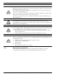
NurseCall Relay Unit 1 Safety instructions | en 5 Safety instructions NOTICE! The user and installer should read and understand this chapter before any intervention on the NurseCall Relay Unit. 1.1 Importance of safety instructions Each safety and protection instruction in this manual must be adhered to in order to avoid personnel injuries, property damages or environmental pollution.
en | Safety instructions NurseCall Relay Unit CAUTION! Maintenance and repairs may only be performed in conformance with the instructions and by authorized technical personnel only. The sole possession of the user manual does not allow the personnel to perform any kind of repair on the NurseCall Relay Unit. Take into account all the warnings and follow all the instructions displayed on the NurseCall Relay Unit and those which are printed in the documentation.
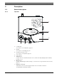
NurseCall Relay Unit Description | en 2 Description 2.1 General description 2.1.1 Top view 7 1 2 3 7 1. 6 5 4 Loudspeaker. See Section 2.2.1 Loudspeaker, page 10. 2. Display. See Section 2.2.2 Display, page 10. 3. Keyboard, under the cover. See Section 2.2.3 Keyboard, page 10. 4. LED Indicator 5. Yellow button Used to view more details about the event or alarm currently displayed (date and time, position, etc...). 6. Green button Used to acknowledge an alarm locally, see Section 5.
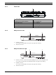
en | Description 2.1.2 NurseCall Relay Unit Bottom view 1 2 3 3 4 6 1. Identification label. 2. Cable channels. 3. 5 Wall mounting holes (distance between holes, 157 mm). See Section 3.2.3 Wall installation, page 14 for a detailed description. 4. ON/OFF switch. 5. LINE socket, used for firmware update. See Section A.5.1 LINE socket (unit bottom), page 34 for wiring. 6. 10V AC socket. See Section A.5.2 Power socket (unit bottom), page 34 for wiring. F.01U.252.722 | V1 | 2011.
NurseCall Relay Unit 2.1.3 Description | en 9 Front view 1 1. 2.1.4 LED Indicator Status LED Standby mode (normal operation) Green (permanent) Backup battery low Green (blinking) Power supply disconnected Green (flashing) Help, assistance or fire Red (blinking) Relay Unit rear view 1 1. 2 RS-485 connector. See Section A.5.4 RS-485 socket (unit rear), page 34 for wiring. 2. 2.1.5 Antenna connector Relay Plus Unit rear view 1 1.
en | Description NurseCall Relay Unit 2.2 Detailed description 2.2.1 Loudspeaker When one of the following alarms or messages is received by the NurseCall Relay Unit, the internal loudspeaker is activated until acknowledgement. 2.2.
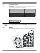
NurseCall Relay Unit Description | en Keys 11 Function Access to the printer/display setup (Relay Plus Unit only) See Section 4.4 Printer/display setup on the Relay Plus Unit, Page 22. Increase the volume of the loudspeaker. See Section 5.1 Adjusting the loudspeaker volume, page 25. Decrease the volume of the loudspeaker. See Section 5.1 Adjusting the loudspeaker volume, page 25. Scroll down to the previous alarm/event. See Section 5.2 Consulting the alarm or event buffer, Page 25.
en | Description 2.2.4 NurseCall Relay Unit RS-485 interface One NurseCall Main Unit and up to 32 NurseCall Relay Units can be connected by a RS-485 bus. The bus must be connected to pins 2 and 5 of the RS-485 socket. For connector wiring, see Section A.5.4 RS-485 socket (unit rear), page 34. NOTICE! Keep polarity equal when connecting further units to the RS485 bus! NOTICE! Maximum RS485-bus length: 1200 m. Use only one twisted pair cable for the interconnection.
NurseCall Relay Unit Installation | en 3 Installation 3.1 Unpacking 13 The NurseCall Relay Unit is carefully packed for transportation. The components contained in the box are protected, but should be handled with care. Store the packaging material for further use (storage or transport). 1. Take all components out of the box and place the NurseCall Relay Unit on the working space. 2. 3. Check each component in the box, in accordance with the list of contents below.
en | Installation NurseCall Relay Unit 3.2 Installation 3.2.1 Generalities Install the NurseCall Relay Unit in a dry place, away from any source of heat. Tools required: 3.2.2 – Torx T20 screwdriver. – Torx T10 screwdriver. Installation on a piece of furniture It is recommended to place the NurseCall Relay Unit on a non-slippery surface. However, do not place anything (blanket or lace) on top of the unit. 3.2.
NurseCall Relay Unit 3.2.5 Installation | en 15 Connecting to the mains The NurseCall Relay Unit is powered by an adaptor (230/10 VAC or 115/10 VAC). CAUTION! In case of a different supply, the equipment must fulfill isolation requirements according to EN60950 standard (last edition). 1. Plug the power adaptor into a power outlet placed near the unit. It should be easily accessible at any time. 1 2. Connect the cable to the socket labeled 10V AC (1), under the unit.
en | Installation 3.2.6 NurseCall Relay Unit Setting the jumpers on the communication board on the Relay Plus Unit 1. 2. Disassemble the unit; see Section 6.5.1 Disassembling the unit, page 29. Remove the communication board; see Section Removing the communication board, page 29. 3. Set the jumpers as required in your configuration. By default the jumpers are set for connection to a Display Zettler.
NurseCall Relay Unit 3.2.7 Installation | en 17 Connecting the RS-485 One NurseCall Main Unit and up to 32 NurseCall Relay Units can be connected to an RS-485 bus. Please contact a specialist for a correct installation. See Section A.5.4 RS-485 socket (unit rear), page 34 for connector wiring.
en | Installation 3.2.8 NurseCall Relay Unit Connecting the RS-232 to the Relay Plus Unit Connect the printer or display device to the 9-pole SUB-D connector (1) at the rear part of the housing of the Relay Plus Unit. 1 For connector wiring, see Section A.5.3 RS-232 socket (Relay Plus Unit rear), page 34. 3.2.9 Setting the 100 Ohm termination jumper Within the NurseCall Main or Relay Units, the RS-485 interface can be configured with a jumper. 1. 2.
NurseCall Relay Unit Programming | en 4 Programming 4.1 Generalities 4.1.1 Using the keyboard 19 Open the cover carefully and use the keyboard. P O N T O F F OK To access the special settings programming, press C three times quickly. See Section 4.3 Special settings, page 21 for more details. 4.1.2 Exit and cancel entries 4.1.3 Press once or several times. Key not allowed If you have pressed a key by mistake during the programming, a high-pitched beep is generated. 4.1.
en | Programming NurseCall Relay Unit 4.2 First use 4.2.1 List of original factory settings Parameter Original Factory Setting Page * Locating mode On 20 * Identification number No value 20 Assistance and fire priority No 21 Special texts in German No 22 Printer/display setup (Relay Plus Unit only) None 22 Speaker volume Midrange 25 * Locating mode and identification number are set at first use. To change a value, reset the unit. See Section 4.3.
NurseCall Relay Unit Programming | en 21 Manual selection of the NurseCall Main Unit 5.a. Scroll with and to set manually the identification number. Confirm with or the Green button. The Relay Unit signalizes that it is not connected to the RS-485 bus. NurseCall RELAY UNIT OFF !!! 5.b. Connect the NurseCall Relay Unit to the RS-485 bus. The identification number is now displayed at the bottom right. 4.3 Special settings After pressing three times quickly, you can enter special codes.
en | Programming 4.3.4 NurseCall Relay Unit Assistance and fire non priority This command sets the assistance call and the fire alarm as non-priority calls. This means that the last alarm is displayed, whatever its type. This is the default value. 1. Type the code 123992. The unit plays a melody and a confirmation message is displayed. ASSISTANCE & FIRE NONPRIORITY 4.3.5 Special texts in German This command sets special texts in German.
NurseCall Relay Unit 4.4.2 Programming | en 23 Selection "None" if you have selected None, press ¬ RS-232 Output None to confirm. £ In this case, there will be no printer/display output. This is the default setting. 4.4.3 Selection "Printer" if you have selected Printer, press ¬ RS-232 Output Printer 1. ¡ Set the printing of all the daily messages sent by transmitters. ¬ Printer 24h printed ?:YES 4.4.4 to confirm. 2. Scroll with 3. Confirm with ¡ and to select YES or NO.
en | Programming NurseCall Relay Unit c. Choose 0 to 9 characters for the criterion, followed by 0 to 9 spaces. Default values are 2 characters + 1 space. 7. Repeat the operation for a. the floor (0 to 3 characters and 0 to 9 spaces), by default 2 characters and 1 space b. the room (0 to 3 characters and 0 to 9 spaces), by default 2 characters and 1 space c. the bed (0 or 1 character), by default 1 character.
NurseCall Relay Unit Operation | en 5 Operation 5.1 Adjusting the loudspeaker volume 25 When the NurseCall Relay Unit is in standby mode: 5.2 Press to increase the volume. Press to decrease the volume. Consulting the alarm or event buffer The NurseCall Relay Unit uses an alarm buffer and an event buffer for display indication.
en | Operation 5.2.1 NurseCall Relay Unit Switching between alarm and event buffers indication The alarm buffer is indicated by default. If you are in the event buffer, the unit changes automatically to the alarm buffer after 1 minute without activity. If there are no entries in the alarm buffer, the display shows the actual date and time. 5.2.2 To switch from alarm to event buffer and vice versa, press Scroll the alarms or the events with Scroll the alarms only with the Green button.
NurseCall Relay Unit Operation | en 27 Third information block 8. position of the last passed beacon, visible in all display modes. If no beacon is registered or if the alarm is sent outside of the range of a beacon, the POS 000 will be displayed. In the alarm buffer, the total number of entries is indicated on top at the right. You can immediately see how many alarms are active. In this example, there are a total of three alarms in the alarm buffer.
en | Maintenance NurseCall Relay Unit 6 Maintenance 6.1 Checking the system Check the correct function of your NurseCall system. 6.2 Perform periodically an alarm test. Monitoring the power supply In case of a power failure, the NurseCall Relay Unit emits a beep and the following message is displayed alternatively with the date and time display: Main Power Error The backup battery ensures that the NurseCall Relay Unit remains operational even in the case of a power failure.
NurseCall Relay Unit 6.4 Maintenance | en 29 Cleaning Avoid using cleaning products or detergents. Wipe off your NurseCall Relay Unit occasionally with a dry cloth. 6.5 Parts replacement 6.5.1 Disassembling the unit Removing the antenna 1. Remove the antenna (1) and its adapter (2) or (3). 1 3 1 2 Removing the communication board DANGER! Do not damage the battery cable, its connector (7) or the serial communication board connectors. 1.
en | Maintenance 6.5.2 NurseCall Relay Unit Backup battery replacing Important Safety Instructions The battery should charge for 24 hours before using the NurseCall Relay Unit for the first time, after replacing the battery or after a long power shortage. Battery type is 6V NiMH. NOTICE! The battery will charge correctly between 5 ºC (41ºF) and 45 ºC (113 ºF). A battery that is new or that has not been used for a long time can have reduced capacity at first use.
NurseCall Relay Unit 7 Disposal | en 31 Disposal The NurseCall Relay Unit is marked with a crossed-out wastebasket symbol. This means that, at the end of its lifetime, the product should be disposed separately from ordinary household waste in accordance with the EU Directive 2002/96/EC. The product and its accessories should be delivered to an appropriate collection facility that ensure recycling, treatment and an environmentally compatible disposal.
en | NurseCall Relay Unit A Appendix A.1 Electrical specifications A.2 A.3 Voltage 230 or 115/10VAC Current 280 mA Frequency 50/60 Hz Power 2.8 W max. Dimensions and weight Casing dimensions [mm] Depth 220 Width 180 Height 40 Antenna [mm] Height 400 Casing weight [g] Weight (including antenna and power supply adaptor) 740 Environmental conditions Operating temperature F.01U.252.722 | V1 | 2011.
NurseCall Relay Unit A.4 | en 33 List of criteria Criterion Number Alarm (A) or Event (E) Comment ERROR 00 A System malfunction, e.g. component defective PERSONNEL A 01 E Coded key active (N46) LOW BATTERY 02 A Battery at low level (Transmitter) ACK.
en | NurseCall Relay Unit A.5 Connectors A.5.1 LINE socket (unit bottom) LINE socket Wiring 1. Flash Data GND 2. Not used 3. Not used 4. Not used 5. Not used 6. Flash Data IN/OUT 1 2 3 456 A.5.2 Power socket (unit bottom) 10V AC socket Wiring 1. Not used 2. AC-1 10-12VAC 3. AC-2 4. GND 1 2 3 4 A.5.3 RS-232 socket (Relay Plus Unit rear) RS-232 socket Wiring 1. --- 54321 2. TXD (RXD) 3. RXD (TXD) 9876 4. --5. GND 6. --7. --8. --9. --- A.5.
Bosch Security Systems Robert-Bosch-Ring 5 85630 Grasbrunn Germany www.boschsecurity.