9/14CBi, 14/19CBi, 19/24CBi WALL MOUNTED BOILERS FOR CENTRAL HEATING AND INDIRECT SUPPLY OF DOMESTIC HOT WATER INSTALLATION AND SERVICING INSTRUCTIONS Worcester supports the Benchmark code of practice This appliance is for use with Natural Gas or LPG (Cat II 2H3P). 9/14CBi GC NUMBER 41 311 50 (N.G.) 9/14CBi GC NUMBER 41 311 51 (LPG) 14/19CBi GC NUMBER 41 311 52 (N.G.) 14/19CBi GC NUMBER 41 311 53 (LPG) 19/24CBi GC NUMBER 41 311 54 (N.G.) 19/24CBi GC NUMBER 41 311 55 (LPG) APPLIANCE OUTPUTS 9/14CBi N.G.
Contents 1. 2. 3. 4. 5. 6. 7. 8. 9. 10. Electrical. . . . . . . . . . . . . . . . . . . . . . . . . . . . . . . . . . . . . . . Page 10 11. Installing the Appliance . . . . . . . . . . . . . . . . . . . . . . . . . . Page 15 12. Commissioning the Appliance . . . . . . . . . . . . . . . . . . . . Page 23 13. Instructions to the User . . . . . . . . . . . . . . . . . . . . . . . . . . Page 24 14. Inspection and Service. . . . . . . . . . . . . . . . . . . . . . . . . . . Page 24 15. Replacement of Parts . .
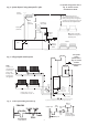
working at a gauge pressure of at least 0.35bar above the relief valve setting if on a sealed system. Where a storage system will not have a vent to atmosphere the installation must comply with Building Regulations and Water Company bye-laws. If connecting to an existing system the local authority should be informed. Fig. 1. Water flow diagram. Pipes Return Flow 2.7 Flue There are 3 fluing options available. (i) Rear Only Flue Kit.
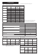
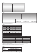
3. Technical Data The data plate is fixed to the inner casing cover. Table 1. Factory set at maximum input NOMINAL BOILER RATINGS (10 Minutes After Lighting) BURNER APPLIANCE OUTPUT INPUT (Net) GAS RATE PRESSURE kW kW m bar. m3/h 14.00 15.28 11.0 1.62 9/14CBi NG 11.50 12.70 7.3 1.41 9.00 10.11 4.5 1.07 14/19CBi NG 19.05 20.57 11.5 2.18 16.52 17.96 8.5 1.90 14.00 15.38 6.0 1.63 23.45 25.74 12.0 2.72 19/24CBi NG 21.25 23.35 9.8 2.47 19.05 21.16 7.8 2.24 14.00 15.28 27.2 0.63 9/14CBi LPG 12.00 13.18 20.4 0.
Table 4 FLOW - COPPER TAILS MECHANICAL SPECIFICATIONS 22mm RETURN - COPPER TAILS 22mm GAS INLET 15mm COMPRESSION CASING HEIGHT 600mm CASING WIDTH 390mm CASING DEPTH 260mm WEIGHT - LIFT 9/14CBi 28kg 14/19 & 19/24CBi 33.5kg WEIGHT - PACKAGED 9/14CBi 41kg 14/19 & 19/24CBi 47kg Table 5 PRIMARY WATER CAPACITY PERFORMANCE SPECIFICATIONS 9/14CBi 1.6 litres STATIC HEAD 14/19 & 19/24CBi 2.1 litres MINIMUM 1.
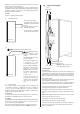
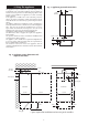
4. Siting The Appliance Fig. 3. Appliance pipework connections The appliance may be installed in any room subject to the requirements of the current IEE regulations and, in Scotland, the relevant electrical provisions of the Building Regulations with respect to the installation of appliances in rooms containing baths or showers.
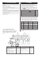
5. Flue terminal positions 6. Air Supply The flue system must be installed following the requirements of BS5440:1. The standard flue kit length is 425 - 725mm. Extension kits for flues up to 3.0m are available. A rear flue suitable for walls from 220 - 375mm thick is available which can be contained within the boiler casing. The terminal must not cause an obstruction nor the combustion products a nuisance.
7. System 8. Domestic Hot Water The system must comply with requirements of BS6798 and BS5449. General: The appliance is only suitable for connection to indirect fully pumped sealed and open vent systems. The minimum static head is 1.2m and the maximum is 30m. The pump MUST be wired to the boiler control to ensure that the pump-overrun function operates to prevent the risk of overheating and hence nuisance shutdown.
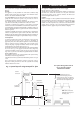
For system wiring please refer to Fig. 10. and the controls manufacturers details. Fig. 6. System layout if using Honeywell 'S' plan Feed and Vent Cistern Primary S.H. cold feed (15mm min.) S.H. – Minimum static head 1.2m measured from the highest point in the heating system (top surface of the appliance S.H. or highest point in the heating system) to the water level in the feed and expansion tank Domestic hot water cylinder Heating vent (22mm min.) Diverting valves N.B.
9. Gas Supply 10. Electrical The gas supplier must be contacted to check the suitability of the appliance for the local gas supply conditions before connecting the appliance. The 19/24CBi appliance requires a maximum of 2.72 m3/h of natural gas (G20), 1.05 m3/h propane (G31). The 14/19CBi appliance requires a maximum of 2.18 m3/h of natural gas (G20), 0.84 m3/h propane (G31). The 9/14CBi appliance requires a maximum of 1.62 m3/h of natural gas (G20), 0.63 m3/h propane (G31). Refer to Table 1.
Fig.10. Boiler wiring diagram Fan Air pressure switch NC white NO grey COM brown of these connections is not * Polarity important.
Fig.11 .
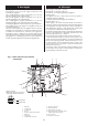
Fig. 12a. Boiler Assembly 9/14CBi Shown set for Rear Only flue kit 26 18 17 20 19 21 16 22 1 15 2 14 3 13 25 4 12 11 24 5 23 6 9 10 1. 2. 3. 4. 5. 6. 7. 8. 9. 10. 11. 12. 13. 7 8 14. 15. 16. 17. 18. 19. 20. 21. 22. 23. 24. 25. 26.
Fig. 12b. Boiler Assembly 14/19 and 19/24CBi Shown set for horizontal flue or vertical flue 17 18 20 19 16 21 22 23 15 1 2 14 3 13 27 26 4 12 11 5 25 6 24 10 8 9 1. 2. 3. 4. 5. 6. 7. 8. 9. 10. 11. 12. 13. 14. Inner case J bolts and wing nuts (2) Combustion chamber cover Burner Burner fixing screw Control knob Indicator lights Base/controls fixing screw Cabinet fixing screw Gas valve Spark electrode Burner injector Temperature sensor Overheat thermostat 7 15. Air pressure switch 16.
Fig. 13b . Flue and wall plate 11. Installing The Appliance NOTE: READ THIS SECTION FULLY BEFORE COMMENCING THE INSTALLATION To install a boiler with a rear only flue refer to Section 11.1. To install a boiler with a to Section 11.2. telescopic horizontal flue kit refer To install a boiler with a vertical flue refer to Section 11.2. and the literature with the flue kit. 11. Installation of the Boiler with a Rear Only Flue Kit Flue fixing position 11.
Fig. 14a . Rear only flue assembly 3 L+5 6 Tape 2 1. 2. 3. 4. 5. 6. 4 1 5 Telescopic flue assembly Terminal assembly Flange / flue assembly Indents Wall mounting plate Flue tube with fixing bar 11.1.6 Install the Boiler Fig. 14b . Rear of casing IMPORTANT: Thoroughly flush the system before connecting the boiler. Any system cleanser must be flushed from the system before adding any inhibitor. (i) Lift the boiler onto the wall mounting plate. See Fig. 15.
Fig. 15 . Fixing the appliance to the wall mounting plate. 2 6 5 8 1 1. 2. 3. 4. 5. 6. 7. 8. 7 Telescopic flue assembly Wall mounting plate Fixing or security screw Levelling feet (2) Restrictor plate with rectangular hole Gasket Flue fixing screws Flue tube with fixing bar 3 4 Fig. 16 . Fan/Flue hood Assembly with Rear Only Flue Kit 5 NOTE: The polarity of wires is not important 6 11 9 —ve 1 10 +ve 8 7 + 4(—) (clear tube) 2 12 3 (+) (red tube) 17 1. 2. 3. 4. 5. 6. 7. 8. 9. 10. 11. 12.
11.1.8 Completion of the Installation Fig.17 . Mains electricity and controls connections. Check that all the gas and water connections have been tightened. 10 11 12 13 Lower the base plate/control panel. Refer to Fig. 17. The permanent mains and switched live supply to the boiler must come from the system junction box. Refer to Fig.11. A 4 core cable is recommended. 9 14 1 Feed the 4 core cable and the pump cables through the bracket and secure in the cable clamp. Refer to Fig. 17.
Fig.19. Flue turret fixing and combustion sensing point (iii) 1 1 2 8 7 1. 2. 3. 4. 5. 6. Flue spigot fixing screws Flue spigot Restrictor ring (if required) Gasket Flue spigot fixing holes Combustion sensing point 7. Clamping ring 8. Fixing screw hole The method of installation of the flue system may be varied to suit the actual site conditions. The instructions for connecting and fixing the ducts must, however, be strictly followed. Remove all packing material from the flue components.
11.2.6 (i) Telescopic Horizontal Flue Kit up to 750mm in Length 11.2.8 Flue Bends 90° and 45° directional bends are available. A maximum of two 45° or 90° bends may be used in addition to the first bend on the flue turret. A 90° bend is equivalent to 750mm of straight duct. A 45° bend is equivalent to 375mm of straight duct. The standard flue can be telescopically adjusted to any length between 425mm and 725mm. It will only be necessary to cut the standard assembly if L<425mm.
Fig. 24 - Elbow to Flue Turret Assembly. Fig.26 . Terminal assembly for internal fitting of the flue. 120mm Tape 5 1 100mm Flue Turret 4 3 2 Bend 1. Flue centring ring 2. Air duct 3. Flue duct 4. Rubber sealing gasket 5. Flue Terminal 11.2.9 Vertical Adaptor for Horizontal Flues An adapter is available for an initial short section of vertical flue. Refer to Fig. 25. Measure and cut the flue as described in Section 11.2.7.
Fig.29 . Flue Turret Fixing . 11.2.12 Installation of Flue onto Boiler (i) Fit the clamping ring around the flue spigot but leave loose. From the inside push the assembly through the wall. Align the flue turret and push fully onto the spigot on the appliance. (ii) Slide the clamping ring into position so that the hole in the spigot lines up with the hole in the ring. Tighten the ring in this position. Through the fixing hole screw the self drilling screw into the flue (see Fig. 29).
12. Commissioning The Appliance Fig. 31. Gas Valve. 2 1 Cleansing and Inhibiting a Central Heating Installation in compliance with Benchmark It is accepted good practice in compliance with BS 7593, Pas 33 and Benchmark, to cleanse both an existing central heating system when fitting a replacement boiler, and when fitting a new central heating system. Then treat with a 'Corrosion Protector.' Worcester recommend only products from water treatment manufacturers participating in Benchmark.
12.8 Central Heating Check that the external controls are calling for heat to the heating circuit. Check that all the radiators heat up evenly. If necessary carefully vent. pressure falls. 13.5 Explain that regular servicing, of a maximum of 12 months between services, will maintain the safe and efficient operation and extend the life of the appliance. Worcester can offer a comprehensive maintenance contract. 12.9 Balance the system to give the correct temperature differential. Refer to Table 3.
Fan Horizontal Flue. Remove the combustion chamber cover. Carefully pull off the electrical connections and the tubes from the air flow detector. Loosen the two clamps to remove the fan . Refer to Fig 34. 14.4 Component Cleaning Do not use a brush with metal bristles to clean components. Clean the fan taking care not to block air flow detector. Clean the burner to ensure that the blades are clear. Do not use a metal probe to clean the injector. Clean the electrodes and check the alignment.
15.3 Draining the Appliance Isolate the appliance. Remove the casing. Refer to Section 14.3. Fit a tube to the drain connection from the system (top connection only) and open the tap. Refer to Fig 34. Close the tap when the flow has stopped. IMPORTANT: A small quantity of water will remain in some components. Protect any electrical components when removing items that might retain water. 15.
Fig. 34 . Inner Casing - Gas and Electric Controls. 9/14CBi shown. 17 16 18 19 20 15 21 22 23 1 11 14 2 13 3 12 1. 2. 3. 4. 5. 6. 7. 8. 11 14 4 10 8 5 7 9 8 6 7 25 9. 10. 11. 12. 13. 14. 15. 16. 17. 18. 19. 20. 21. 22. 23. 24. 25.
Alter the red arrow if a new setting is made. The adjustment screw must be sealed by a dab of paint to stop unauthorized adjustment. Switch off the appliance, disconnect the pressure gauge and tighten the test point screw. Refer to Fig. 31. Check for gas soundness. 15.4.1 Gas Valve NOTE: If the left hand clearance is >50mm then the gas valve can be replaced with the burner and combustion chamber cover in place by unscrewing the four extended screws at the manifold on the outside of the inner casing.
15.4.5 Control Board 15.4.6 Fan Lower the base plate/control assembly and carefully disconnect the plug-in connector and all the electrical connections. Refer to Fig. 35. Release the five clips and lift out the control board. Refer to Fig. 35. Pull out and replace, if necessary, a failed fuse. Remove the inner casing and combustion chamber cover . Remove the fan as described in Section 14.3 Inspection and Servicing. The flue hood gasket should be replaced if it is damaged or has deteriorated.
15.4.7 Air Flow Sensor 15.4.10 Air Pressure Switch Remove the fan as described in 14.3. Unscrew and withdraw, through the fan outlet, the air flow sensor. Refer to Fig .38 and 38a. The detector is 'handed' - do not force it into place. Noting the position of each pressure tube carefully disconnect the tubes and electrical connections from the switch. Unclip and remove the switch if there is more than 50mm clearance. Refer to Fig.40.
15.4.11 Combustion Chamber Insulation The insulation pads are manufactured from a material in accordance with COSHH. Remove the casing, inner casing cover and combustion chamber cover. Front Insulation: Unscrew the clamp at the top of the combustion chamber cover to replace insulation. Fig. 41. Heat Exchanger Baffles in Position on the Heat Exchanger Side Insulation: Release the clip at the bottom and slide out the insulation.
(VI) Transfer the spark and flame electrode assemblies to the new burner blade assembly. Refer to Sections 15.4.2 - 4 for details of positions. These instructions should only be read if converting appliance from Natural Gas to LPG or vice versa. (VII) Fit the new burner blade assembly into the appliance not forgetting to re-connect the electrode leads. Only components supplied by Worcester, Bosch Group should be used. (VIII) Refit the combustion chamber front and inner case cover. 16.
17. Short Parts List Key No. G.C. No. 1 E60-473 2 E60-474 3 E60-475 4 E60-476 5 6 7 8 9 10 11 12 13 14 15 16 17 18 19 20 21 22 23 E60-477 E60-478 E60 479 E60-480 E60-481 E60-482 E60-483 E60-484 E60-485 E60-486 E60-487 E60-492 E60-493 375 696 E60-498 E60-499 E60-500 E60-503 E60-504 Part Manufacturer’s Reference Burner Assembly NG 9/14CBi Burner Assembly LPG 9/14CBi Burner Assembly NG 14/19, 19/24CBi Burner Assembly LPG 14/19, 19/24CBi Injector Burner 3.4mm NG 9/14CBi Injector Burner 2.
Mains 230V supply Boiler demand from system junction box AND User control knob ON BOILER HEAT DEMAND 34 Temperature Sensor disconnected Boiler overheat lockout light (flashing) FAIL re-attempt ignition (MAX 4 PASS times) FAIL Ignition PASS sequence Boiler cycles to satisfy temperature set by facia control knob Overheat thermostat trip.
19. Fault Finding NOTE: This fault finding information is for guidance only. Worcester, Bosch Group cannot be held responsible for costs incurred by persons not deemed to be competent. The electronic control for this boiler incorporates three lights: Boiler demand, flame on and lockout. These form the basis for this fault finding guide. To use this guide, select box below which represents the light situation during your fault, then refer to the appropriate section.
FAIL POINT A Gain access to the control board. Is there 230V at connector X1 between pins SL & N? No No boiler demand from the heating system. Investigate system. Yes Replace control board. NOTE: It is normal to see only a demand light if the boiler is hot and the burner has temporarily shut off. Ensure boiler is cool and user control set to maximum. Gain access to the control board. Is there 230V at connector X1 between pins 'PERM LIVE' & 'N'? No Yes FAIL POINT B Create a new demand.
FAIL POINT C Is the boiler in a very cold environment i.e is the primary water temperature below 5°C? No Demand light has failed. Replace control board if it is considered a problem. Yes Boiler is running in 'Autofroststat' mode. Is the system fully water pressurised and is all air vented? No Rectify fault/leak. Yes The system should have a bypass fitted as described in Section 7. SYSTEM and Figs. 5, 6 & 7. Is bypass fitted and correctly adjusted? No Add or adjust system bypass.
Is the gas supply connected and at the correct pressure? No Rectify gas supply problem. Yes Remove boiler casing. Reset and restart the boiler. Can a flame be seen through the spyglass? Note: there is a 20 second delay from fan on to spark. No TURN OFF GAS SUPPLY. Remove inner casing cover. Reset and restart boiler. Does a spark occur across the electrodes? No Are the electrodes and gap and connections in good order? Yes FAIL POINT E 'BURNER LOCKOUT' Yes During spark period is there 216V D.C.
FAIL POINT F Delivered primary water temperature always too hot. (Over 85°C) Delivered primary water temperature appears too low with control knob set to maximum. (Less than 75°C) Move control knob to lower setting. Such a fault is likely to be caused by one or more of the following: Low gas pressure Partially blocked flue Partially blocked heat exchanger Blocked/dirty burner Gas valve sticking Control board fault Faulty themister 39 Check thermister sensor/heat conductive paste.
BENCHMARK No. GAS BOILER COMMISSIONING CHECKLIST COLLECTIVE MARK BOILER SERIAL No. CONTROLS NOTIFICATION No.
SERVICE INTERVAL RECORD It is recommended that your heating system is serviced regularly and that you complete the appropriate Service Interval Record Below. Service Provider. Before completing the appropriate Service Interval Record below, please ensure you have carried out the service as described in the boiler manufacturer s instructions. Always use the manufacturer s specified spare part when replacing all controls SERVICE 1 DATE SERVICE 2 DATE ENGINEER NAME COMPANY NAME TEL No.
This manual is to be used in conjunction with the variant part number of the bar code below: www.worcester-bosch.co.uk Bosch Group Worcester, Bosch Group, Cotswold Way, Warndon, Worcester WR4 9SW. Telephone: 01905 754624. Fax: 01905 753130. Technical Helpline 08705 266241. Worcester, Bosch Group is a trading name of BBT Thermotechnology UK Limited.