TECHNICAL MANUAL FOR AFTER SALES AND SERVICE TECHNICIANS DOMESTIC HOT WATER HEAT PUMP This document is confidential and restricted to exclusive use by the official technical assistance of Bosch in the countries of destination of this product.
1. INTRODUCTION ............................................................................................ 3 1.1 GENERAL DESCRIPTION ............................................................................................................ 4 1.2 PRODUCT PRESENTATION ......................................................................................................... 5 1.3 WORKING PRINCIPLE .............................................................................................................
1. Introduction Domestic Hot Water Heat Pumps (DHW-HP), with or without air connections ducts, use the heat existing in the surrounding air, or the waste heat from the indoor air, as energy source for DHW preparation. These machines are commonly known as air-source hot water heat pump and they are energy-saving and environmentally friendly equipment with a plug-and-play system structure and easy maintenance.
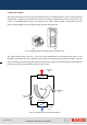
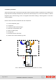
1.1 General description This model of domestic hot water heat pump provides hot water for residential purposes, using a closed refrigerant unit filled with a refrigerant gas (R134a). This ensures the energy production taking out the energy from a cold source - air, and delivering this energy to a secondary circuit – water - where a simple circulation pump, ensures water movement through a heat exchanger, heating the water stored in a tank. (a) (b) Pict.
1.2 Product presentation Apart of the main function of the heat pump operation with the required mandatory components of an air/water heat pump with electrical backup installed for any eventual need, the heat pump has, in some of the models, an internal integrated coil for external energy source as integration with existent standing or wall hung boiler or even solar energy installation.
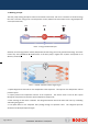
1.3 Working principle The heat pump working principle is based on the transfer of the heat, and not on conversion of electrical energy into heat. It removes energy from a low temperature source (ambient air) and transfers it into a high temperature source (hot water tank). Pict.4 – Energy and electrical input Electricity is used to upgrade the comfort (temperature) of heat energy and not to generate heat energy.
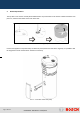
2. Heat Pump Elements The top EPP cover must be carefully disassembled before any intervention on the module. Follow instructions from picture 6, existent in the sticker on the back of the tank. Pict.6 – Disassembling of top cover In front of the appliance and protected by an EPP front panel (fixed to the tank with 4 magnets), it is possible to find the magnesium anode and the electric resistance for backup. Pict.
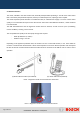
2.1 Anode Protection The anode, installed in the water heater tank, will slowly dissipate whilst protecting it. The life of the water heater tank is ensured by the periodical inspection, done by an authorised person, replacing it when required. The anode inspection period shall take in consideration that, for softened water supply or in areas of worse water quality, it is recommended to inspect it more often and for some other critical different situations, a water treatment is recommended.
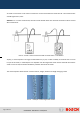
An anodic current meter can be used to measure the current and evaluate the anode time life. The measured value shall be higher than 0,3 mA. Attention: For a correct measurement, the tank must be full with water! The electrical connection must be ensured after measurement. Pict.
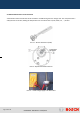
2.2 Electrical Resistance and Thermostat A thermostat control activates the electric resistance of 2kW immerged in the storage tank. This component has a safety function set at 90ºC, limiting the temperature from an external source (solar, boiler, etc, …) to 80ºC. Pict.12 – Electric Resistance (2 kW) Temperature adjustment Pict.13 – Bipolar thermostat interfaces Pict.
Pict.15 – Check continuity between terminals After any intervention in the anode and/or thermostat, ensure the correct assembly with correspondent washer and assembly of the protection cover. Pict.16 – Protection cover of the thermostat and electrical backup group In the most recent production models, order to increase robustness of the tank in the models with coil, the electric heater of the models HP 270-1E 1 (with coil), is from was isolated.
2.3 Coil for external source of energy The coil integrated in the storage tank of some of the models (see table 1), can be used to combine the heat pump with a back up energy system like solar, boiler, etc. In case the coil will not be used, do not remove the caps from the coil inlet and outlet connections. This will avoid thermal losses due to the contact of the air in the coil with the surrounding hot water in the tank.
Components checking procedure Unit o Inspect all the elements in the installation place o Check the airflow clearances o Check the output temperature o Clean the evaporator coils as following: – Clear the outside of the coil of debris – Vacuum the coil fins using a soft bristle brush attachment – take care to avoid bending the fins – Spray water from the inside to the outside of the coils to remove stuck debris using a hose and spray gun – Vacuum or remove by hand any remaining debris in the unit o
The list of available material (separate document) must be checked in order to choose the adequate material for repairs in the refrigeration circuit. 3.
The compressor and condenser are needed to enable the same refrigerant to be used several times. The cost of compressing and condensing the vaporized refrigerant is far less than the cost of often renewing of the refrigerant. To maintain the difference in pressure between the condenser and the evaporator caused by the compressor, an expansion valve is needed. The expansion valve separates the high pressure from the low pressure side in the system.
Model - 10ºC to +35ºC The working principle of this model is the same as for +5ºC to +35ºC, with exception of the defrosting process, which is done through a solenoid valve, activated by the control unit, depending on the temperature measured by the NTCs, assembled in the evaporator fins and sensing the air temperature which will be detailed further in this manual. Pict.
3.3 Main Components Data Evaporator Suppliers: Behr, Mahle Specification from supplier: - Cooling capacity of 1.
Specifications from supplier: - Liquid line filter drier Dry filter - Drying agent in bulk - Low pressure drop Supplier: Honeywell - Hermetic construction (Series FF) - Temperature range: TS = -40ºC / +80ºC MOP at +15ºC - TEV with built in orifice of 2 mm, bulb Ø of 12 mm, internal equalization Expansion valve and fixed superheating setting. Supplier: Honeywell Specifications from supplier: (Series TLK) - Thermostatic expansion valve for serial produced systems. Note: - Max.
3.4 Electrical Measurements Scheme A Scheme B Pict.
Position (Scheme Nr) Model Model +5ºC / +35ºC -10ºC / +35ºC A15 X A2 X A20 / B16 A1 / B11 X Component Characteristics X Expansion valve TLK 2.
The NTC’s listed in the table above, are supplied in a common cable with the following configuration: (A) (B) (A) model -10ºC / +35ºC (B) model +5ºC / +35ºC Pict.24 – NTC cables The NTC sensors for air, cold and hot water are the same, but give different information to the software in the electronic control. Following table indicates the measurable resistance value to check and identify each proper function. These NTC sensors are a 10kΩ type.
55 2957 2986 60 2521 2488 65 2157 2083 70 1853 1752 75 1598 1481 80 1384 1258 85 1202 1072 90 1048 917 95 916 788 100 804 680 105 707 588 Table 3 – NTC characteristic Pict.25 – Electrical cables connection on HMI Electrical Supply connection Pump Connection Capacitor Connection Fan Connection Fan Capacitor Pict.
4. Components Overview 4.1 Compressor The compressor is usually driven by an engine and this unit compresses or transports the refrigerant through the system. The main principle is that the refrigerant is compressed as it is sucked into the compressor in a gaseous form at a low temperature from the evaporator. Pict.27 – Compressor It is then forwarded in gaseous form at a high temperature and high pressure to the condenser. The dimensioning of the compressor has to be adapted to the system size.
Electric test to the compressor: The compressor has some electrical connections and a temperature limiter thermostat that ensure its protection. Using a multimeter, is possible to control its functionality, nevertheless the HMI will detect if compressor is running. Cables and cover protection have clear identification of the different connections. C S R – Main electro valve S – Auxiliary electro valve R R C – Common Pict.
Electric test to compressor: Check earth connection C – chassis ≠ 0 S – chassis ≠ 0 R – chassis ≠ 0 Attention: In case of continuity the compressor is defected Pict.30 – Testing of compressor Thermal Protection This function is ensured by a bimetallic temperature limiter which opens its contact when high temperature (T=160ºC ±10ºC) is reached during operation. Pict.
(a) Open contact (b) Close contact temperature activation – T≥160ºC normal operation – T<70ºC Pict.32 – Functional position After any intervention, ensure correct cover protection assembly. Pict.33 – Cover of electrical elements from compressor Capacitor of Compressor Pict.34 – Discharging capacitor In case of check capacitor, discharge electric charge with a resistance of 20k and 2W Not OK - ∞ OK - 0Ω Pict.
4.2 Filters and driers Moisture or water vapour may cause problems in any type of refrigerant system, because moisture may freeze in the orifice of the expansion valve, causing corrosion of metal parts and wet the motor of the compressor, damaging it (motor burnout and oil sludge). On the other hand, foreign matter may contaminate the compressor oil and become lodged in valve parts, making system inoperative.
evaporation cooling. In order to achieve optimum cooling capacity in the evaporator, the refrigerant flow is controlled by the expansion valve or orifice tube. The component achieves high durability thanks to welded stainless steel head and stainless steel diaphragm and contains the gas charge for quick response time adapted to small evaporators. ATTENTION: In case of replacement, the component should be protected from the heat during soldering process. Pict.37 – Expansion valve (cut view) 4.
Pict.38 – Pressure switch from Danfoss Various shunt relays are triggered by the pressure switch in order to guarantee safe and effective use of the refrigerant system under all conditions. Through this process, individual system components are switched on and off according to the defined pressure points. The pressure switches can fail due to contacting problems or soiling. Regular system servicing prevents failure. Pict.39 – Pressure switch, filter drier and expansion valve group 4.
Pict.40 – Fan and Evaporator 4.6 Condenser Domestic Hot Water Side (Secondary circuit) Refrigeration side (Primary circuit) Pict.41 – Condenser The condenser is required to cool down the refrigerant heated up by compression in the compressor. The hot refrigerant gas flows into the compressor, thereby dissipating heat to the other side of the plate. As it cools, the refrigerant pressure falls and the refrigerant state changes from gaseous to liquid.
Pict.42 – Plate heat exchanger condenser working principle In case of hard water, the condenser shall be periodically cleaned in order to avoid obstruction. Pict.43 – Plates of the heat exchanger and counter-flow representation 5. Human Machine Interface – HMI User manual must be used to verify functions and active parameters. For the service mode, following instructions should be considered. The control unit has a standby consumption of 3W.
Display (LCD) Selection Buttons Pict.44 – HMI Panel Entrance in the service mode: Press “Menu” + “Ok” button during more than 5 sec Pict.45 – Enter in service mode Table 4 includes the meaning of each parameter visible on the service mode that can be used by technicians for diagnostic and repair actions.
X X 6d Number of air defrost procedures + X 7d Number of gas defrost procedures + last 10 failures with error code indication X X 1F until 10F Attention: + (If no error is memorized, display shows “-- --“) X X EE X X AL X X E cleaning of the historical memory of the last 10 failures test display (all segments ON) Exit Service Mode (for FD<202, minimum press time of 3sec) Table 4 – Service Mode Parameters Working modes: Error Mode OFF Mode Reset function by pressing OK button for
The working principle is based in the following considerations: Switch OFF No Reaction from system Switch ON (main switch in the back of HP) Error in memory? no yes Stand-by mode (1) 1) Error Mode For Stand-by Mode (1) Stand-by mode HMI actuation LCD Backlight ON LCD Backlight OFF (after 15 sec without any selection) Active Operation Mode Temperature of the Tank Clock & Day Function Temperature Selection Page 34 from 63 Temperature Blinks until confirmation with OK button 6720649497 SM HP
Conditions for operation: The heat pump compressor is activated according the following conditions and according control unit settings defined.
Full mode until Ttop = 60ºC Electric Heater mode until Ttop = 70ºC Legionela stops when: TTop≥70ºC or TBottom ≥ 60ºC (or time in Legi > 24h) Conditions for air-defrost sequence: Air defrost sequence is activated in both +5ºC or -10ºC models when T air > 5ºC and < 10ºC for more than 60 min: Tbottom < 20ºC (defrost every 90 min) Tbottom < 35ºC (defrost every 150 min) Tbottom < 60ºC (defrost every 240 min) Compressor OFF Fan ON during 10 min Water Pump OFF Conditions for gas-defrost sequence: Gas Defro
6. Maintenance and preventive actions 6.1 Corrosion Corrosion is the term for a chemical or electrochemical reaction between a material, usually a metal, and its environment, which produces a deterioration of the material and its properties. A metal can be exposed to many different kinds of corrosion and below we can see some examples of the ones applicable to this type of brazed plate heat exchangers.
The corrosive effect of natural water can vary considerably with its chemical composition. Water quality is of great importance to avoid corrosion in the plate heat exchanger (condenser). City Water Normally is controlled and of good quality. Well water Is usually fairly cold and clean, which implies that it has a low biological content. However, the concentration of scale forming salts (calcium and magnesium sulphates and carbonates) can sometimes be very high.
Free chlorine (Cl2) Hydrogen Sulfide (H2S) Free (aggressive) carbon dioxide (CO2) Total Hardness (ºdH) Nitrate (NO3) Iron (Fe) Aluminium (Al) Manganese (Mn) > 300 0 0/+ <1 + + 1–5 + 0 >5 0/+ 0/- < 0.05 + + > 0.05 + 0/- <5 + + 5 – 20 + 0 > 20 + - 4.0 – 8.5 + + < 100 + + > 100 + 0 < 0.2 + + > 0.2 + 0 < 0.2 + + > 0.2 + 0 < 0.1 + + > 0.
o pH o calcium content o alkalinity o ionic strength of the water (Is) Please note: - For water analysis, mg/l is equivalent to ppm - The relation between calcium and calcium carbonate is 40g CA 2+ ≃ 100g CaCO3 - TDS = salt content (mg/l) or possibly the conductivity x 0.63 (μS/cm) If Is<0, the water has a tendency to be corrosive. If Is>0, the water has a tendency to cause scaling. Eliminating the scaling problems There are several ways to eliminate the scaling problem.
Check position*, connection, continuity Cables * Ensure distance to copper pipes Manual activation Safety valve Pre-charge verification (vessel without Expansion vessel water pressure) Leakages, lack or defective insulation Pipe work Cleaning of calc deposition, inspection of Heating element integrity Table 6 – Resume of main maintenance actions The main connections are through thread connection with washer, however and for the connections of the flexible hose with o’ring connection, the lubric
In the NTC sensor, in contact with the pipe of cold water from the bottom of the storage tank, and in the NTC sensor, in the pocket of the hot water from the top of the tank, the thermal paste “Wacker” (part nr 8 719 918 658) must be used to ensure an efficient contact and consequent efficient temperature sensing. Condenser Maintenance - Descaling procedure The process of descaling in the condenser of plate heat exchanger type can be done in the place, with no need of removing the component.
Pict.49 – Kaloxi descaling liquid to clean plate heat exchangers Descaling process: - Close cold water inlet and open hot water tap to take out pressure from the top of the heat pump; - Remove connection in the top of the condenser plate heat exchanger to allow the outlet of the water and then, remove the connection in the bottom; Pict.
Pict.51 – Flexible hose of descaling pump connection - Put the pump in operation, taking in consideration that the flow must be, inside the heat exchanger, in the opposite direction of the water. The direction can be defined in the pump on the correspondent lever, as shown in picture 51. Pict.52 – Flexible hose of descaling - Leave the pump in operation for some minutes to remove lime scale.
Pict.53 – Example of a manual air purge Evaporator Maintenance The fins of the evaporator should be cleaned and aligned in order to allow an adequate air flow through the complete surface, ensuring the correct function of the evaporator, and the consequent energy transfer to the refrigerant gas. Pict.54– Detail of the fins and 3 passages evaporator (cut model) Pict.
Pict.56 – Example of cleaning and purifier spray for evaporators application For the maintenance, diagnostic and performance analysis of the heat pump module and its refrigerant circuit, following information must be taken in consideration. On chapter 7, additional information is described to help the understanding of the operation of the circuit.
7.
Code E07 – Only for internal technical use Code E08 – Only for internal technical use ONLY FOR models, produced till February 2012 Code E09 Lock Out Error Failure in Compressor System Condition: Appliance was turned on, is in standby and fault was displayed before operation 1 Contacts Open on safety elements - thermal protection Check Continuity 2 Contacts Open on safety elements – high pressure switch Check Continuity 3 Contacts Open on safety elements – low pressure switch Check Continuity High
2 Contacts Open on safety elements – high pressure switch Check Continuity 3 Contacts Open on safety elements – low pressure switch Check Continuity Fault in the low pressure side 1 High pressure loss in the air ducts Check ducts and accessories equivalent length 2 Failure in fan operation Check fan operation and connection 3 Leakage in the refrigeration circuit Check with an leakage detector the origin of the leakage, repair and refill circuit.
7.1 Failures prevention and detection The design data supplied by Bosch must be known by authorized service partner’s technicians, in order to prevent and avoid the following problems, nevertheless, the service partner is responsible to prepare technicians in such a way that the following problems will never happen in the field with an end user.
7.2 Evaporator under performance The evaporation process is sensitive and potentially unstable. Minor changes in performance have major effect on the system performance (COP). A one-degree change in the evaporation temperature changes the COP by approximately 3% and an unstable process could also cause the evaporation temperature to fluctuate, with a potential risk of freezing in the evaporator. The critical parameter for the system performance is the saturated pressure at the compressor inlet.
Pict.59 – Position of the bulb and insulation 7.3 Condenser under performance The condensing process is normally stable, and will not cause any major disturbances on the system performance. The evaporator performance can have influence in the condenser performance, and the problems are usually manifested as an increased pressure head. Check Points: - Check the installation visually (refrigerant and water circuits are connected in counter-current mode with the refrigerant inlet at the top.
7.4 Other recommendations and definitions Pict.
7.5 Service Needs Using pressure manometers and thermometer The normal measuring equipment is a service pressure gauge and preferably some type of thermometer. Data is collected using fixed gauges and connecting service gauge to the available connections to the service in the system. Portable instruments as refrigerant analysers are also available and give already all data needed with possibility of printing the report. Pict.
During the process of repairs and manometer connections to the pressure gauges, check the eventual existence of micro-leakages with an adequate equipment in order to avoid the lost of refrigerant gas to the atmosphere and consequent malfunction in the appliance operation after your visit. Pict.63 – Example of an electronic leakage detector from Testo 7.6 Terminology Overheating of the refrigerant gas In the fundamental process, the gas entering the compressor is assumed to be dry and saturated.
Efficiency Definition The basic compressor-driven refrigeration cycle consists of one compressor, two heat exchangers (evaporator and condenser) and a throttling device (expansion valve). These components form the circuit in which the refrigerant circulates and the cycle operates between the two pressure levels P1 and P2, and the temperatures T1 and T2, where T1 > T2. Pict.
In the ideal cooling circuit the superheat is 0°C.
Pict.66 – Expansion valve and bulb position Sub-cooling The sub cooling is the difference between the condensing temperature and the liquid line temperature. The condensing temperature is determined with a pressure gauge and the liquid line temperature is measured with a digital thermometer Takes place in the condenser and indicates the liquid refrigerant cooling after it has changed into liquid state.
8. Appendix Guide with list of material for service partners The following list is only a guideline with the main important elements to make repairs in the refrigeration circuits of Heat Pumps. The material should be adequate for the proper use of refrigerant gas. Depending on the type of machine, other tools can be needed and the list should be adapted to the available equipment in the countries.
Soldering equipment To soldering components in repairs in the refrigeration circuit. Thermal paste (protect heat transmission to surrenders) To avoid damages in the components near of the soldering points Nitrogen Kit For circulation inside of refrigerant circuit during brazing process Manometers group (R134a) For the measurements of refrigeration operation pressures and temperatures, for the purpose of refrigerant transfer and for system evacuation, a service gauge manifold is used.
Recovery Equipment To use during phase out of the gas to deliver to a recovery cylinder used in the field to recover, recycling, reclamation and evacuation of refrigeration systems 1) Recovery unit ‘oil less’ for commercial refrigeration 2) Condenser and ventilator 3) High and low pressure gauges 4) Refrigerant inlet and outlet valves 5) Inline filter-drier Refrigerant recovery cylinder To use after take out gas of the refrigerant unit and used to deliver in the adequate entities for recycling process.
Brush / cleaning tools 1) steel brush Inner and outer cleaning and finishing works of soldering Cleaning / protection sprays - - sprays for disinfection: to pulverize in the evaporator fins, avoiding the deposition of bacteria’s in the air flow way spray to retire dirtiness, grass and other elements from fins and not aggressive for aluminum. Gas leakage detectors Electronic leak detector for HC refrigerants Reversible ratchet handle To remove magnesium anode and replace it.
Testing equipment - Electronic thermometer - sensor probes to detect temperatures in the circuit 1) Electronic thermometer for up to two probes, measuring range –50°C to 1150°C 2) Electronic thermometer equipped with three probes 3) Electronic hand thermometer with one probe, measuring range – 50°C to 150°C Digital clamp on meter Non contact ampere measurement, voltage and resistance measurement LCD display and holding function for easy reading 1) Ampere measuring clamp 2) LCD display 3) Measurement sele