
Data Sheet


Fire Alarm Systems | D341 Four‑wire Duct Smoke Detector Housings
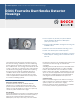
D341 Four‑wire Duct Smoke Detector
Housings
www.boschsecurity.com
u For 1 ft (30.5 cm) to 10 ft (3 m) ducts with air
velocity between 300 ft/min to 4000 ft/min
(1.52 m/s to 20.3 m/s)
u Easy duct tube installation through the housing cuts
installation time.
u Detector test and reset without removing covers
u Clear cover allows quick visual inspection
u Tube filters, dust immune smoke detector, and easy
disassembly for cleaning reduce maintenance time
and cost
The D341 Duct Smoke Detector Housings mount on
the ducts of heating, ventilation, and air conditioning
(HVAC) systems to monitor the presence of smoke in
the conditioned air. The housing works with all 24 VDC
or VAC or 120 VAC, UL Listed four‑wire control panels.
The efficient housing design samples the air passing
through a duct and detects potentially hazardous
conditions. When smoke is detected, the detector
sends an alarm signal to the control panel or HVAC
control equipment that initiates the necessary action
to control air handling systems.
Functions
Alarm and Trouble Indication
A D344‑RT Remote Test Kit, a D344‑RL Remote
Indicator Kit, or a DRA‑5 Remote Annunciator can
provide remote LED indication of alarm and trouble
status. The red LED lights for an alarm. An open loop
causes the yellow Trouble LED to light.
Air Sampling
Use the duct detector housings in air handling systems
with ducts between 1 ft (30.5 cm) and 10 ft (3.05 m)
wide and air velocities between 300 ft/min and
4000 ft/min (1.52 m/s to 20.3 m/s). Air is forced into
the detector through an air sampling tube, tested, and
returned to the duct through an exhaust tube
(supplied).
Sampling tubes should extend across the width of the
duct. Bosch Security Systems, Inc. offers sampling
tubes in three different sizes. Combined or cut the
tubes to make other lengths. Sampling tubes over 3 ft
(91.4 cm) must be supported at the end opposite the
duct detector. Sampling tubes are provided with an
end plug that must be installed in the open end.
System Testing
Place an external magnet on the detector housing or
switch a signal from a remote test station to test the
system (requires an external 24 V supply).
Reset the system by power shutdown or if a D344‑RT
is connected, use the key-operated switch.