
Installation Guide

FPP-RNAC-8A-4C | Operation and Installation Guide |
.
Bosch Security Systems, Inc. | 8/09 | F01U025431-02 3
Contents
1.0 Overview ...........................................................4
1.1 Module Control...................................................4
1.1.1 Option Bus Control ...........................................4
1.1.2 Conventional NAC Input Control ...................4
1.2 Output Bell Operation .......................................4
1.3 Power Management..........................................4
1.4 Low AC Line Detection .....................................4
1.5 Ground Fault Monitoring...................................4
1.6 Circuit Supervision ............................................4
1.7 Overvoltage Supervision ..................................4
1.8 Expander Supervision.......................................5
1.9 Auxiliary Power Supply.....................................5
2.0 Installing the FPP-RNAC-8A-4C...................5
2.1 FPP-RNAC-8A-4C Board Installation.............6
2.2 Enclosure Installation........................................6
3.0 Wiring the FPP-RNAC-8A-4C........................8
3.1 AC Power Connections ....................................8
3.2 Battery Connections (24 VDC Only).............10
3.3 Option Bus Connections.................................14
3.4 NAC Input Connections..................................14
3.5 Trouble Relay Connections ...........................15
3.6 Auxiliary Output Connections ........................15
3.7 NAC Output Connections...............................15
3.7.1 NAC Circuits....................................................15
3.7.2 Auxiliary Circuits .............................................16
3.7.3 EOL Reference Programming........................16
4.0 DIP Switch and Option Bus Settings........17
4.1 Switch S1...........................................................17
4.2 Switch S2...........................................................18
4.3 Conventional (Polarity Reversal) Inputs 1
and 2..................................................................19
4.4 Option Bus Address ........................................20
4.5 NAC Input Variable .........................................20
4.6 AC Fail Time Delay .........................................20
5.0 FPP-RNAC-8A-4C Local Status Display ..21
6.0 Specifications.................................................23
Figures
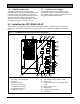
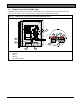
Figure 1: FPP-RNAC-8A-4C Remote NAC
Power Supply Board.................................. 5
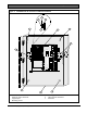
Figure 2: FPP-RNAC-8A-4C Enclosure and
Board Installation ....................................... 7
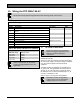
Figure 3: AC Power Connections............................. 9
Figure 4: Install Ferrite Core ..................................... 9
Figure 5: Battery Connections Inside
FPP-RNAC-8A-4C Enclosure ................ 10
Figure 6: Battery Connections Using an External
Battery Case ............................................. 11
Figure 7: Wiring the Option Bus ............................. 14
Figure 8: Wiring the NAC Inputs............................. 14
Figure 9: Wiring the Trouble Relay ........................ 15
Figure 10: Wiring the Auxiliary Outputs................... 15
Figure 11: Wiring the NAC outputs and EOL.......... 16
Figure 12: Auxiliary Power Configuration................ 16
Figure 13: FPP-RNAC-8A-4C LEDs ........................ 22
Tables
Table 1: Wire Gauge Calculations................................ 8
Table 2: Wire Gauge Table (based on solid wire)...... 8
Table 3: Standby Time Calculation............................. 12
Table 4: Calculating the Required Battery Size........ 12
Table 5: Standby Load Battery Capacity (in ampere-
hours [Ah]) ................................................ 13
Table 6: Alarm Load Battery Capacity (in ampere-
hours [Ah])) ............................................... 13
Table 7: DIP Switch S1 Settings ................................. 17
Table 8: DIP Switch S2 Settings ................................. 18
Table 9: Using Conventional Inputs 1 and 2 to
Operate Outputs (Switch 2,
Position 0) ................................................. 19
Table 10: Local Status Display LED Functions......... 21
Table 11: Specifications ............................................... 23