
Installation Guide


FPP-RNAC-8A-4C | Operation and Installation Guide | 3.0 Wiring the FPP-RNAC-8A-4C
8 Bosch Security Systems, Inc. | 8/09 | F01U025431-02
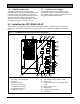
3.0 Wiring the FPP-RNAC-8A-4C
All terminals are fully protected against electrostatic discharge (ESD) and transients.
Use wire gauge based on Table 1 and Table 2. The terminals can accommodate up to 12 AWG (2.0 mm) wire.
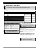
Table 1: Wire Gauge Calculations
Line No. Description Calculation
Value
1 Guaranteed minimum NAC voltage at full load.
27.4 V
2
Minimum operating voltages (largest value of appliance on
circuit)
3 Maximum wiring voltage drop
Subtract line 2 from line 1.
4 Total load for a given NAC
5 Maximum allowable line resistance
Divide line 3 by line 4.
6 Total wiring run length (feet)
7 Total wire needed
Multiply line 6 by line 2.
8 Maximum wire resistance per foot
Divide line 5 by line 7.
9 Choose a wire size with a resistance per foot less than Line 7.
Table 2: Wire Gauge Table (based on solid wire)
AWG B&S Gauge Ohms per Foot
12 (2.0 mm) 0.00162
14 (1.6 mm) 0.00258
16 (1.3 mm) 0.00409
18 (1.0 mm) 0.00651
NFPA 72 requires the use of 18 AWG
(1.0 mm) or larger diameter wire in fire
applications.
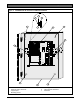
3.1 AC Power Connections
Disconnect all power (AC and battery)
before servicing the FPP-RNAC-8A-4C.
Wait 60 sec before handling any
connections.
AC Power runs to the L (Hot VAC), G (Ground), and
N (Neutral) terminals.
120 VAC or 240 VAC with 8 A capacities should feed
the local power supply. The output voltage is a filtered
27.6 VDC (500 mV ripple maximum) under all
conditions.
A trouble condition is registered, but not indicated, if
AC power fails. A programmable time delay (refer to
Section
4.6 AC Fail Time Delay on page 20) allows
the indication of AC Failure to be delayed by 0, 6, 12,
or 24 hrs. The default is 0 hrs.
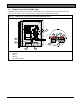
Refer to
Figure 3 on page 9 for wiring details.
Remember to select the appropriate
voltage range for the AC input before
applying any power to the product.