
Installation instructions


Page 6
Before you begin
Tools and Parts Needed
• Measuring tape
• Pencil
• Phillips screwdriver (Posidrive) #2
• Drill with the following bits:
5
⁄16” (7.9 mm) and
3
⁄8”
(9.5 mm)
• Spirit-level
• Aluminum tape (DO NOT use insulating tape)
• Exhaust channel (conguration depends on the
installation situation)
• Additional sheet metal screws (if necessary for
installation of the exhaust air duct)
• Saw
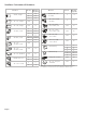
Parts Included
• Extractor hood with fan, back-pressure ap
• Lamp, already installed
• Metal grease lter
• Flue duct
• Drill template
• 1x angle bracket for the ue duct
• Installation manual and instructions for use
• 6x screws, 5x45 mm
• 8x screws, 4x8 mm
• 2x washers
• 2x hollow wall plugs, 8x40 mm
• 4x hollow wall plugs, 10x50 mm
• Torx adapter, 10 & 20
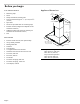
Appliance Dimensions
24" (610 mm) or
30" (762 mm) or
36" (914 mm)
A
19
11
/
16
"
(500 mm)
7
7
/
8
"
(200 mm)
4
5
/
8
"
(118 mm)
10
3
/
4
"
(273 mm)
13
3
/
16
"
(335 mm)
5"
(126 mm)
A Only for circulating-air mode:
*Max. 42 9/16” (1081 mm)
*Min. 28 1/4” (718 mm)
Only for ducted operation:
*Max. 38 7/8” (988 mm)
*Min. 24 9/16” (625 mm)