
Installation instructions


Page 9
Installation Procedure
The ducting from this fan to the outside of the building has
a strong effect on the air ow, noise and energy use of the
fan. Use the shortest, straightest duct routing possible for
best performance, and avoid installing the fan with smaller
ducts than recommended. Insulation around the ducts can
reduce energy loss and inhibit mold growth. Fans installed
with existing ducts may not achieve their rated airow.
Ensure duct joints and exterior penetrations are sealed
with caulk or other similar material to create an air-tight
path and to minimize building heat loss and gain, and
reduce the potential for condensation.
Place/wrap insulation around duct and/or fan in order to
minimize possible condensation buildup within the duct,
building heat loss and gain.
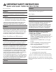
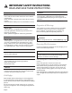
CAUTION
Ensure that there are no electric wires, gas or water pipes
in the area where holes are to be made.
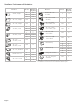
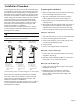
Roof
Venting
Wall
Venting
Non Vented
(Recirculating)*
A. Roof ca
p
B. 8" (20.3 cm)
round vent
C. Seal duct joints
with duct tape/
caulk
A. Wall cap
B. 8" (20.3 cm)
round vent
C. Seal duct joints
with duct tape/
caulk
A. Diverter
B. 8" (20.3 cm)
round vent
C. Seal duct joints
with duct tape/
caulk
A
B
C
A
A
B
C
B
C
*The recirculating version are neither Energy Star nor HVI certied.
Ensure duct joints and exterior penetrations are sealed
with caulk or other similar material to create an air-tight
path and to minimize building heat loss and gain, and
reduce the potential for condensation.
Place/wrap insulation around duct and/or fan to in order to
minimize possible condensation buildup within the duct,
building heat loss and gain.
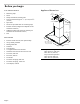
Preparing the installation
1. Mark a vertical center line on the wall from the ceiling
to the lower edge of the extractor hood.
2. Align the drill template on the center line and the
bottom edge of the extractor hood and glue on.
3. Mark positions for the screws and the contour of the
attachment area.
4. Mark holes for the ue’s angle brackets. The center of
the angle bracket is marked with a hole. Place the
angle brackets in the center of the center line, align
them horizontally and mark the positions of the holes.
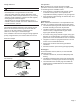
Fitting the wall retainer
1. Drill holes with Ø 5/16” (7.9 mm) for the angle bracket.
2. Press in the wall plugs ush with the wall.
3. Screw screws (5x34 mm) into the wall plugs by hand
in order to spread the plugs apart.
4. Unscrew screws.
5. Screw on the angle bracket for the ue duct.
Making the ceiling breakthrough
1. Using a spirit level, extend the center line of the drill
template to the ceiling.
2. Mark the ceiling breakthrough (Ø 8 1/2” (216 mm)) at
least 4 5/8” (117 mm) away from the wall.
Making the wall breakthrough
1. Using a spirit level, extend the center line of the drill
template to the ceiling.
2. Depending on the curved section of the wall
breakthrough (Ø 8 1/2” (216 mm) mark at least
26 1/2” (660 mm) above the bottom edge of the
extractor hood.