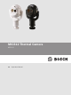
MIC612 Thermal Camera MIC612 en Operation Manual
MIC612 Thermal Camera Table of Contents | en 3 Table of contents 1 Safety 5 1.1 About this Manual 5 1.2 Legal Information 5 1.3 Safety Precautions 5 1.4 Important Safety Instructions 5 1.5 Customer Support and Service 7 2 Unpacking 8 2.1 Parts List 8 2.2 Additional Products Required 8 2.3 Additional Tools Required 9 3 Product Description 10 4 Electrical Connections 11 4.1 About the MIC Shielded Composite Cable 11 4.
en | Table of Contents MIC612 Thermal Camera 9 On-Screen Display (OSD) Menus (Bosch Protocol) 42 9.1 Camera Setup Menu 44 9.2 Thermal Camera Setup Menu 46 9.3 Lens Setup Menu 48 9.4 PTZ Setup Menu 50 9.5 Display Setup Menu 52 9.6 Communication Setup Menu 54 9.7 Alarm Setup 55 9.8 Language Menu 61 9.9 Diagnostics Menu 62 10 On-Screen Display (OSD) Menus (Pelco Protocol) 66 10.1 Bosch Menu 68 10.2 Camera Setup 69 10.3 PTZ Setup 70 10.4 AUX Setup Menu 72 10.
MIC612 Thermal Camera 1 Safety 1.1 About this Manual Safety | en 5 This manual has been compiled with great care and the information it contains has been thoroughly verified. The text was complete and correct at the time of printing. Because of the ongoing development of products, the content of the manual may change without notice.
en | Safety MIC612 Thermal Camera Caution! TO REDUCE THE RISK OF ELECTRIC SHOCK, DISCONNECT THE POWER SUPPLY BEFORE ! OPENING THE POWER SUPPLY UNIT. POWER DISCONNECT: POWER SUPPLY UNITS HAVE POWER SUPPLIED WHENEVER THE POWER CORD IS INSERTED INTO THE POWER SOURCE. Warning! ! INSTALLATION SHOULD BE CARRIED OUT BY QUALIFIED PERSONNEL ONLY, IN ACCORDANCE WITH THE NATIONAL ELECTRIC CODE, ANSI/NFPA, CANADIAN ELECTRICAL CODE, AND ALL LOCAL COUNTRY CODES.
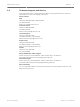
MIC612 Thermal Camera 1.5 Safety | en 7 Customer Support and Service If this unit needs service, contact the nearest Bosch Security Systems Service Center for authorization to return and shipping instructions. Service Centers USA Telephone: 800-366-2283 or 585-340-4162 Fax: 800-366-1329 Email: cctv.repair@us.bosch.com Customer Service Telephone: 888-289-0096 Fax: 585-223-9180 Email: security.sales@us.bosch.com Technical Support Telephone: 800-326-1450 Fax: 585-223-3508 or 717-735-6560 Email: technical.
en | Unpacking MIC612 Thermal Camera Unpacking 2 – This equipment should be unpacked and handled with care. Check the exterior of the packaging for visible damage. If an item appears to have been damaged in shipment, notify the shipper immediately. – Verify that all the parts listed in the Parts List below are included. If any items are missing, notify your Bosch Security Systems Sales or Customer Service Representative. – Do not use this product if any component appears to be damaged.
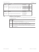
MIC612 Thermal Camera Unpacking | en Quantity Product 1 per camera Shielded Composite Cable for MIC612 cameras (See the model numbers and lengths at right.) Quantity Product 1 per camera Power Supply Unit (PSU) for MIC cameras Part Number Size MIC-THERCBL-2M 2m MIC-THERCBL-10M 10 m MIC-THERCBL-20M 20 m MIC-THERCBL-20M 25 m 9 Part Number MIC-240PSU-2, MIC-115PSU-2, MIC-24PSU-2 2.
en | Product Description 3 MIC612 Thermal Camera Product Description MIC Series 612 cameras are high-performance, weatherproof, ruggedized, fully functional day/ night PTZ cameras that have been designed to offer a reliable, robust, and high-quality surveillance solution for extreme security applications. MIC612 models have a 36x optical zoom (12x digital) and flexible mounting options (upright or inverted) to achieve the perfect field of view.
MIC612 Thermal Camera Electrical Connections | en 4 Electrical Connections 4.1 About the MIC Shielded Composite Cable 11 All connections (power, telemetry, video) to the MIC camera are provided through the screw terminal connections in the MIC power supply. MIC shielded composite cables are multiconductor cables of various lengths (and gauges ranging from 14 - 18) that provide all power, video, and telemetry connections between the MIC PSU and the MIC camera.
en | Electrical Connections MIC612 Thermal Camera Figure 4.2: MIC shielded composite cable connected to a MIC612 camera 4.2 Composite Cable Color-coding The standard color coding used in MIC composite cables is as follows: Figure 4.
MIC612 Thermal Camera Electrical Connections | en Camera Signal Name Description Cable 13 Cable Wire Color Connector Pin 11 Full Duplex Rx B+ Telemetry I/O to RS-422/485 White Half Duplex Tx/Rx B Bosch Security Systems 12 Power Input 2 Low Voltage Power Input Green 13 Power Input 1 Low Voltage Power Input Red Operation Manual 2016.03 | 2.2 | F.01U.249.
en | Install the MIC (standard) PSU MIC612 Thermal Camera 5 Install the MIC (standard) PSU 5.1 MIC PSU Overview Caution! ! Use only the power supply specified for your specific model of camera. Bosch provides a range of power supply units (PSUs) for MIC Series cameras. These units have a variety of common voltages and provide all the connections needed for power, telemetry and video. Model Number Input Voltage Dimensions Weight (H x W x D) MIC-24PSU-2 24 VAC 90 x 260 x 160 mm 3.2 kg (7.
MIC612 Thermal Camera Install the MIC (standard) PSU | en 15 terminated) wires for wiring into terminals in the MIC PSU. The composite cable consists of two pairs (24AWG) plus 4 cores of (22 AWG), 2 cores of (24 AWG), and one coax core for the video signal to a maximum distance of 25 m. Notice! Bosch Security Systems does not recommend using the shielded composite cable for distances greater than 25 m between the MIC camera and the MIC power supply.
en | Install the MIC (standard) PSU MIC612 Thermal Camera Figure 5.
MIC612 Thermal Camera Install the MIC (standard) PSU | en 17 Fuse Ratings 5.5 The MIC PSUs for MIC612 cameras have four (4) off 20 mm fuses (numbers 13 - 16 in the figure “Layout of MIC-240PSU-2 and MIC-115PSU-2”) in fuse holders. The ratings for these fuses are fixed on the low voltage secondary side but change with input voltage on the high voltage primary side.
en | Install the MIC (standard) PSU MIC612 Thermal Camera Figure 5.4: Layout of MIC-240PSU-2 and MIC-115PSU-2 No.
MIC612 Thermal Camera No. Install the MIC (standard) PSU | en PCB Description/Function of Type of Connection/ Marking Connection / Terminal Terminal 13 FS2 Fuse 2 - Primary protection -- 14 FS1 Fuse 1 - MIC camera protection -- 15 FS3 Fuse 3 - Heater protection 1 -- 16 FS5 Fuse 5 - Heater protection 2 -- 17 -- Earth termination post Ring terminal 5.
en | Install the MIC (standard) PSU MIC612 Thermal Camera Notice! Do not connect MIC IR units to a MIC PSU with the heater option enabled as this can damage the cameras. Ensure that an IR power supply is used with a MIC IR camera unit. Heaters are available for MIC612 cameras only. Caution! ! Bosch recommends using an uninterruptible power supply (UPS) in connection with a MIC camera/PSU installation.
MIC612 Thermal Camera Install the MIC (standard) PSU | en 21 5. Secure the enclosure to the mounting surface using four (4) M6 stainless steel screws and washers (not supplied), which fit through the large holes in the enclosure. Notice! If you are securing the power supply enclosure in a vertical position (for example, on a wall), one person should hold the enclosure lid while another secures the enclosure body in place, to avoid damage to any part of the enclosure, and/or injury to the installer(s). 6.
en | Install the MIC (standard) PSU MIC612 Thermal Camera PCB Marking Description L Live N Neutral Earth / Ground 11. Remove the brass nut and copper washer from the earth termination post (item 3 in the figure “Mains input with shield removed…”); set these aside. 12. Remove the ring terminal (supplied). 13. Insert the earth core from the mains cord (item 2 in the figure “Mains input with shield removed…”) into the crimp portion (size M6, UL-certified) of the ring terminal and crimp it in place.
MIC612 Thermal Camera Install the MIC (standard) PSU | en 23 Figure 5.8: MIC PSU Enclosure, with cable glands identified Number Description Cable Gland Size 1 Optical Video out M12 2 Composite cable M16 3 Optional switched video output M12 4 Head-end / Telemetry controls M12 18. Connect the shielded composite cable to terminal block HD3 (and, if necessary, HD6 and HD7) following the color coding as shown in the figure below, and printed on the PCB. No ID, Connection/ PCB Mark, .
en | Install the MIC (standard) PSU MIC612 Thermal Camera No ID, Connection/ PCB Mark, .
MIC612 Thermal Camera Install the MIC (standard) PSU | en 25 switched Video Out cable to BNC socket CN3. This second cable provides control for video from both the optical camera and the thermal camera; users can switch between the two cameras. 25. Feed telemetry cable through the bottom-right M12 cable gland (item 4 in the figure “MIC PSU Enclosure, with cable glands identified”). 26.
en | Install the MIC (standard) PSU Signal MIC612 Thermal Camera Pin Number Washer 1 Pump Washer 2 Pump Warning! ! The washer pump terminal is rated only to 24 VAC or VDC maximum voltage and is not suitable for Mains-operated pumps. 4 Test the washer by pressing the red button marked SW1 PUMP ON on the PCB. LED 3 illuminates in response to telemetry commands from the control room to turn on the washer.
MIC612 Thermal Camera Install the MIC (standard) PSU | en 27 Figure 5.9: Position of LEDs - MIC Series power supply PCB Bosch Security Systems Operation Manual 2016.03 | 2.2 | F.01U.249.
en | Install the MIC (standard) PSU MIC612 Thermal Camera Figure 5.10: Position of LEDs - MIC Series IR power supply PCB Number LED Description 1 LED 1 Indicates that 18 VAC is available from the power supply and that the LED 2 supply fuses are intact. 2 LED 3 Illuminates when the washer drive is on. 3 LED 4 Monitors the internally generate +5 V. 4 LED 5 Illuminates when the IR lamp supply is turned on by the camera telemetry. 5 LED 6 Status LED.
MIC612 Thermal Camera Install the MIC (standard) PSU | en 29 Figure 5.11: PCB links set to 0V 3. Break the two solder links and remove any excess solder. 4. Solder the links, using TCW link wire, from the left hand pads to the middle pads. The power supply will now deliver 18 VAC to terminal block HD6. Figure 5.12: PCB links set to 18V Bosch Security Systems Operation Manual 2016.03 | 2.2 | F.01U.249.
en | Install the MIC (standard) PSU MIC612 Thermal Camera 5. Locate the Brown and Grey wires from the composite cable. 6. Connect the heater wires Brown and Grey to terminal block HD6 as labelled on the PCB. The heaters are thermostatically controlled and will automatically turn on at +5 °C (+41 °F) and turn off at +15 °C (+59 °F). 5.11 7. Check all connections. 8. Close the PSU enclosure. 9. Reconnect the power supply to the power source.
MIC612 Thermal Camera Fit the Sunshield (MIC612) | en 31 Fit the Sunshield (MIC612) 6 The MIC612 Sunshield is designed to provide additional protection against direct solar radiation. It is a two-part molding and comes supplied with eight (8) stainless steel stand-offs and eight (8) stainless steel M3 washers and retaining screws. The MIC612 stand-offs are slightly shorter than those for the MIC412 and have gnarled threads at one end. The MIC412 stand-offs are slightly longer and are smooth at one end.
en | Fit the Sunshield (MIC612) MIC612 Thermal Camera To fit the sunshield, follow these steps: 1. Turn on the power to the camera so that you can rotate the camera head up to fit the bottom half of the sunshield (see step 8). 2. Rotate the camera under power—do not rotate by hand—until the bottom of the camera head is facing up. 3. Remove the four (4) retaining bolts from the lid of the camera. 4. Place a stand-off into each screw hole and tighten using a flat head screwdriver. 5.
MIC612 Thermal Camera Getting Started | en 33 Getting Started 7 Install and wire the camera according to the instructions in this manual and in the manuals that accompany the power supply and mounting devices. A typical system includes a keyboard, matrix switcher, monitor, and appropriate wiring connections. Refer to the individual product manuals for complete installation and setup instructions for each of the system components. 7.
en | Getting Started MIC612 Thermal Camera The MIC612 camera can be connected in a 2- or 4-wire mode. Available connection protocols are: Pelco, Bosch OSRD (via a keyboard with RS-485 output), Bicom over serial (via CTFID software; see the CTFID User Manual for installation details), and Forward Vision protocols. Cable / Wire Type Shielded Twisted Pair (STP) System Half-duplex, differential, multidrop Maximum Distance 1219 m (4000 ft) Maximum Baud Rate 57.6 kb Gauge 0.
MIC612 Thermal Camera 7.4 Getting Started | en 35 Setting the Addresses of the Two Cameras of the MIC612 After the MIC612 camera is on, you must set the camera address. The optical camera and the thermal camera of the MIC612 have different addresses. The address of the optical camera is set via the OSD and FastAddress. The address of the thermal camera is set via the OSD and a unique address.
en | Getting Started MIC612 Thermal Camera Notice! If a keyboard is set to a camera number that already has an address, that camera also responds to this command. – ON-998-ENTER: Displays and programs all cameras with or without an address in the system. – ON-997-ENTER: Displays the current address status of all cameras in the system simultaneously. To set an address for a camera without an address: 1. Select the camera number that you want to FastAddress.
MIC612 Thermal Camera Getting Started | en 37 To set FastAddress with a Pelco Keyboard: 1. Press and hold 95-PRESET for two seconds to open the Pelco Setup menu. 2. Move the joystick to select the Command Lock menu. 3. Press the FOCUS or the IRIS button to turn Command Lock to OFF. 4. Move to the FastAddress menu and press the FOCUS button or the IRIS button to open the menu. 5. Use the joystick to enter the unique identifier for the camera. Move the joystick up or down to select the number.
8 en | Controlling the Camera MIC612 Thermal Camera Controlling the Camera The most common ways to control the MIC are: – Using a keyboard and on-screen display (OSD) menus. This method is the most common. See Basic Keyboard Operation, page 38. – Using the Configuration Tool for Imaging Devices (CTFID) software running on a PC with Bilinx or the RS-232/RS-485 communication protocol. Go to www.boschsecurity.com to download the latest version of the software and the CTFID User Manual. – 8.
MIC612 Thermal Camera Controlling the Camera | en 39 Notice! After 4.5 minutes of inactivity, the OSD menu times out and exits without warning. Some unsaved settings in the current menu can be lost. To navigate the OSD menus: 1. Use the joystick to highlight a menu item. 2. Press either the Focus or the Iris key to open a menu item. 3. Follow the on-screen instructions. Note: To select the Exit Menu item from anywhere in the current menu, use the Zoom command. 8.
en | Controlling the Camera MIC612 Thermal Camera Keyboard Command User Action Description 0-Pattern Initiate recording continuous playback based upon Press current Recording setting (A or B) in the Setup Menu. Press and hold Initiate recording based upon current Recording setting (A or B) in the Setup Menu. Press ACK to end recording. 1-Pattern Press Initiate Recording A continuous playback. Press and hold Initiate Recording A. Press ACK to end recording.
MIC612 Thermal Camera Controlling the Camera | en Preset Command Description 94-PRESET Initiates a Preset Tour. 95-PRESET Enables or disables Limit Stops in the Setup Menu for AutoScan. 41 Invokes the Pelco main Setup Menu when pressed for 2 seconds. 96-PRESET Stops a scan. 97-PRESET Initiates FastAddress (Pelco Random Scan). 98-PRESET Toggles the Synch. Mode between Line Lock and Internal (Pelco Frame Scan).
9 en | On-Screen Display (OSD) Menus (Bosch Protocol) MIC612 Thermal Camera On-Screen Display (OSD) Menus (Bosch Protocol) This chapter identifies and describes each OSD menu option, as well as the default setting for each option, for Bosch protocol. For step-by-step instructions, see Common User Commands, page 76 and Advanced Features, page 78. To open the main Setup Menu (locked commands) in Bosch protocol: 1. Press OFF-90-ENTER to turn off the command lock. 2.
MIC612 Thermal Camera On-Screen Display (OSD) Menus (Bosch Protocol) | en 43 Setup Menu Choices: Menu Description Exit Exits the menu. Camera Setup Accesses adjustable camera settings such as: white balance, gain, sharpness, sync, line lock, backlight, shutter, and night mode. Thermal Accesses the settings for the thermal camera. Camera Setup Lens Setup Accesses adjustable lens settings such as: focus, iris, zoom speed, and digital zoom.
9.1 en | On-Screen Display (OSD) Menus (Bosch Protocol) MIC612 Thermal Camera Camera Setup Menu The Camera Setup Menu contains settings that can be changed/customized for the optical (visible) camera. Camera Setup Exit...
On-Screen Display (OSD) Menus (Bosch Protocol) | en MIC612 Thermal Camera 45 White Bal Maintains proper color reproduction (white balance) as the color temperature of a scene changes (for example, from daylight to fluorescent lighting). Option Description Extended ATW (Default setting) Adjusts camera color using extended range. ATW Adjusts camera color constantly. Indoor W.B. Optimizes camera color for typical indoor conditions. Outdoor W.B. Optimizes camera color for typical outdoor conditions.
en | On-Screen Display (OSD) Menus (Bosch Protocol) MIC612 Thermal Camera Sets the limit for sensitivity when the shutter speed is set to Auto SensUP. Options: 2x, 4x, 7.5x, 15x (default setting). Night Mode Selects night mode (B/W) to enhance lighting in low light scenes. Options: ON, OFF, AUTO (default setting). Night Mode Color Determines if color processing remains in effect while in night mode. Options: ON, OFF (default setting).
On-Screen Display (OSD) Menus (Bosch Protocol) | en MIC612 Thermal Camera 47 Adjusts the display mode for the thermal camera. Options: Option Description White (Default setting) Hot objects appear brighter than cold objects. Hot Black Hot Hot objects appear darker than cold objects. Fusion Cold objects appear deep blue or purple or black; hot objects appear yellow. Rainbow Cold objects appear black; hot objects appear red or yellow. Globow Similar to Fusion, without blue or purple.
9.3 en | On-Screen Display (OSD) Menus (Bosch Protocol) MIC612 Thermal Camera Lens Setup Menu The Lens Setup Menu contains lens settings that can be changed/customized. Lens Setup Exit... * Auto Focus: SPOT * Auto Iris: CONSTANT * Auto Iris Level: 8 * Focus Speed: 2 * Iris Speed: 5 * Max Zoom Speed: FAST * Digital Zoom: ON Restore Defaults * = Factory Setting Focus / Iris: Select Auto Focus Automatically focuses on the subject in the center of the screen.
MIC612 Thermal Camera On-Screen Display (OSD) Menus (Bosch Protocol) | en 49 Focus Speed Adjusts the manual focus speed. Sliding scale: – (1 to 15) +. Default setting: 2. Iris Speed Adjusts the manual iris speed. Sliding scale: – (1 to 10) +. Default setting: 5. Max. Zoom Speed Adjusts the manual zoom speed. Options: SLOW, MEDIUM, FAST (default setting). Digital Zoom Enables or disables digital zoom. Options: ON (default setting), OFF. Bosch Security Systems Operation Manual 2016.03 | 2.2 | F.01U.249.
9.4 en | On-Screen Display (OSD) Menus (Bosch Protocol) MIC612 Thermal Camera PTZ Setup Menu The PTZ Setup Menu contains pan/tilt/zoom settings that can be changed/customized. PTZ Setup Exit... * Autopan: 30 deg/sec * Tour 1 Period: 5 sec * Tour 2 Period: 5 sec * PTZ Fixed Speed: 4 * Inactivity: OFF * Inact. Period: 2 min * Autopivot: ON * Orientation NORMAL * Freeze Frame on ON Preposition Tilt Up Limit... Azimuth Zero... Restore Defaults...
On-Screen Display (OSD) Menus (Bosch Protocol) | en MIC612 Thermal Camera 51 Inactivity Selects the mode to which the camera reverts after the period of inactivity set in the inactivity period. Options: Option Description Scene 1 Returns to Preset 1. Prev Aux Returns to previous activity, such as Aux commands 1, 2, 7, 8, 50, or 52. OFF (Default setting) Remains on the current scene indefinitely. Inact. Period Sets the time period of inactivity before the above action occurs.
9.5 en | On-Screen Display (OSD) Menus (Bosch Protocol) MIC612 Thermal Camera Display Setup Menu The Display Setup Menu contains display settings that can be changed/customized. Display Setup Exit... * Title OSD: MOMENTARY * Camera OSD: ON Display Adjust * Azimuth: OFF * Compass: OFF Sector Blanking... Privacy Masking... Edit Sector Title... Edit Scene Title... Restore Defaults... * = Factory Setting Focus / Iris: Select Title OSD Controls how the OSD displays sector or shot titles.
On-Screen Display (OSD) Menus (Bosch Protocol) | en MIC612 Thermal Camera Option Description Up Moves screen title up. Down Moves screen title down. Brighter Brightens the intensity of the on-screen text. Darker Darkens the intensity of the on-screen text. 53 Azimuth Display azimuth/elevation values. Options: ON, OFF (default setting). For more details, refer to Azimuth, Elevation, and Compass Directions, page 80. Compass Displays compass heading. Options: ON, OFF (default setting).
9.6 en | On-Screen Display (OSD) Menus (Bosch Protocol) MIC612 Thermal Camera Communication Setup Menu The Communication Setup Menu contains baud rate and Bilinx control settings. Communication Setup Exit... * AutoBaud: ON * Baud Rate: 9600 Bilinx Restore Defaults * = Factory Setting Focus / Iris: Select AutoBaud Turns on AutoBaud detection, which detects and adjusts the camera protocol and baud rate to match that of the controller. Options: ON (default setting), OFF.
MIC612 Thermal Camera 9.7 On-Screen Display (OSD) Menus (Bosch Protocol) | en 55 Alarm Setup The Alarm Setup Menu contains alarm inputs, outputs and rules. Notice! The maximum number of Alarm Inputs is eight (8), available only on the Alarm and Washer Pump Drive Card (MIC-ALM) (sold separately). This card is available for non-IR power supply units (PSUs) only. IR models only will show Alarm Inputs 1–4 and numbers 5–12 will display NONE.
en | On-Screen Display (OSD) Menus (Bosch Protocol) MIC612 Thermal Camera Multi Alarm Setup Allows setup of multiple alarms. Options: On; Off. Checkbox button to "Select." Inputs Setup Submenu Choices: Inputs Setup Defines physical inputs or events and commands that can be used in a rule. There are twelve (12) alarm inputs available. Inputs 1-8 Defines the type of physical input (dry contact): N.O. (Normally Open) (default setting) or N.C. (Normally closed).
On-Screen Display (OSD) Menus (Bosch Protocol) | en MIC612 Thermal Camera 57 Outputs Setup Submenu Outputs Setup... Exit... 1. NONE 2. NONE 3. NONE 4. NONE 5. NONE 6. NONE 7. NONE 8. NONE 9. NONE 10. NONE 11. NONE 12. NONE Focus / Iris: Select Type Right / Left: Select Mode Bosch Security Systems Operation Manual 2016.03 | 2.2 | F.01U.249.
en | On-Screen Display (OSD) Menus (Bosch Protocol) MIC612 Thermal Camera Outputs Setup Submenu Choices: Outputs Setup Defines physical outputs and keyboard commands for use in a rule. Outputs 1–2 Defines a physical output: N.O. (Normally Open circuit) (default setting) or N.C. (Normally closed circuit). Outputs 3–12 Defines a command output for use in a rule. Option Description None (Default setting) No command defined. Aux On Responds to a keyboard ON command.
MIC612 Thermal Camera On-Screen Display (OSD) Menus (Bosch Protocol) | en 59 Rule Setup Submenu Notice! You can program a total of twelve rules. You must define the inputs and outputs before you program a rule. See Alarm Setup, page 55, to configure alarm inputs and outputs. Rule Setup... Rule 1 Exit... Exit... 1. Rule 1 Enabled Enabled 2. Rule 2 Disabled Input: 3. Rule 3 Invalid NONE 4. Rule 4 Empty NONE 5. Rule 5 Empty NONE 6. Rule 6 Empty 7. Rule 7 Empty Output: 8.
en | On-Screen Display (OSD) Menus (Bosch Protocol) MIC612 Thermal Camera Rule Setup Submenu Choices: Rule Setup Displays the status of rules and lets you add new rules or modify an existing rule. Rule 1-12 Displays the status of a rule on the right side of the menu. Rule status options: Option Description Enabled The rule inputs and outputs are properly defined and the rule is turned on. Disabled The rule inputs and outputs are defined but the rule is turned off.
MIC612 Thermal Camera 9.8 On-Screen Display (OSD) Menus (Bosch Protocol) | en 61 Language Menu The Language Menu contains a list of languages in which the on-screen menus are available. Language Exit... English Spanish French German Portuguese Polish Italian Dutch Russian Czech Focus / Iris: Save and Exit Bosch Security Systems Operation Manual 2016.03 | 2.2 | F.01U.249.
9.9 en | On-Screen Display (OSD) Menus (Bosch Protocol) MIC612 Thermal Camera Diagnostics Menu The Diagnostics menu contains a list of diagnostic tools and events. Most of these menu items are display items only; you cannot select different values to change. Diagnostics Exit... Alarm Status... BIST...
On-Screen Display (OSD) Menus (Bosch Protocol) | en MIC612 Thermal Camera 63 Internal Temp. Displays the current temperature of the camera, in degress Fahrenheit and in degrees Celsius. High Temp Events Displays the number of times that the threshold of high temperature was exceeded. Highest Temp Displays the highest temperature reached, in degrees Fahrenheit and in degress Celsius. Low Temp Events Displays the number of times that the threshold of low temperature was exceeded.
en | On-Screen Display (OSD) Menus (Bosch Protocol) Option Description Off (Default setting) No test pattern is available. MIC612 Thermal Camera Ascending ramp A test pattern appears in the analog and digital data channels, to allow you verify the output of the digital data channel. The figure below is a horizontal slice of the complete image; the pattern repeats 19 times in the complete image.
On-Screen Display (OSD) Menus (Bosch Protocol) | en MIC612 Thermal Camera 65 Alarm Status Alarm Input 6 Open Alarm Input 7 Open Alarm Input 8 Open Alarm Output 1 Open Focus / Iris: Save and Exit Alarm Input 1...8 Displays the status of alarm inputs 1 through 7. High Low Open (Normally Open) Closed (Normally Closed) Alarm Output Displays the status of the alarm output. Bosch Security Systems Operation Manual 2016.03 | 2.2 | F.01U.249.
10 en | On-Screen Display (OSD) Menus (Pelco Protocol) MIC612 Thermal Camera On-Screen Display (OSD) Menus (Pelco Protocol) This chapter identifies and describes each OSD menu option, as well as the default setting for each option, for Pelco protocol. For step-by-step instructions, see Common User Commands, page 76 and Advanced Features, page 78. To open the main Setup Menu in Pelco protocol: Press 95-PRESET for approximately 2 seconds. The screen Setup Menu appears. Setup Menu Exit...
MIC612 Thermal Camera On-Screen Display (OSD) Menus (Pelco Protocol) | en 67 Setup Menu Choices: Menu Description Exit Exits the menu. Command Lock Allows or prohibits accessing locked commands. (If password is set, you are prompted to enter the password. The default setting is ON. Bosch Menu Accesses the full configuration menu and all camera settings. Camera Setup Accesses adjustable camera settings such as White Balance and Night Mode.
en | On-Screen Display (OSD) Menus (Pelco Protocol) 10.1 MIC612 Thermal Camera Bosch Menu The Bosch Menu allows full access to the main Setup Menu and all camera configuration settings. Pelco menu Bosch menu Setup Menu Setup Menu Exit... Command Lock: OFF Exit...
MIC612 Thermal Camera 10.2 On-Screen Display (OSD) Menus (Pelco Protocol) | en 69 Camera Setup The Pelco Camera Setup Menu provides access to camera settings. Camera Setup Exit... * White Bal: OUTDOOR * Night Mode: AUTO * Wiper CONTINUOUS * = Factory Setting Focus / Iris: Select Camera Setup Menu Choices: Menu Description Sub-menu / Description Default Setting Exit Exits the menu.
en | On-Screen Display (OSD) Menus (Pelco Protocol) 10.3 MIC612 Thermal Camera PTZ Setup The Pelco PTZ Setup Menu provides access to the PTZ settings such as tours, scan speed, presets, limit stops, recording, and AutoPivot. PTZ Setup Exit... * Edit Tour 1... * Edit Tour 2... * Tour 1 Period: 5 sec * Tour 2 Period: 5 sec * Scan Speed 30 deg/sec Edit Presets... * Limit Stops: OFF * Recording: “A” * Autopivot: ON * = Factory Setting Focus / Iris: Select 2016.03 | 2.2 | F.01U.249.
On-Screen Display (OSD) Menus (Pelco Protocol) | en MIC612 Thermal Camera 71 PTZ Setup Menu Choices: Menu Description Sub-menu / Description Default Setting Exit Exits the menu. Edit Tour 1 Accesses the Add / Exit: Exits the menu. Remove Scenes On Scene (1 - 5): Adds or removes Standard Tour 1 Menu. scenes from the Standard Tour. Accesses the Edit Custom Exit: Exits the menu. Tour Menu. Scene (1 - 5): Adds or removes Edit Tour 2 scenes from the Custom Tour.
en | On-Screen Display (OSD) Menus (Pelco Protocol) 10.4 MIC612 Thermal Camera AUX Setup Menu The AUX Setup menu provides an area to remain Aux commands. AUX Setup Exit... * WASH WIPE * Alarm Output 2: * Not Set Not Set Not Set Not Set * = Factory Setting Focus / Iris: Select 2016.03 | 2.2 | F.01U.249.
MIC612 Thermal Camera 10.5 On-Screen Display (OSD) Menus (Pelco Protocol) | en 73 Other Menus Menu Description Default Setting Edit Password Sets or displays the password. See Setting Passwords, page 37. FastAddress Sets or changes the address. Software Version Displays the camera software version. Ack and Reset Alarms Acknowledges and resets alarms. If there is no active Not Set alarm input, the OSD displays the following message: “No Active Alarms.
en | Operation of the Thermal Camera MIC612 Thermal Camera 11 Operation of the Thermal Camera 11.1 Switching Video To switch Video Channel 2 between the optical (visible) camera and the thermal camera, enter the Thermal Camera Setup menu of the OSD, select the option Second Channel Video, and then toggle to the appropriate choice. 11.
MIC612 Thermal Camera 11.4 Operation of the Thermal Camera | en 75 Triggering Alarms On Detection of Objects Outside of Set Thermal Temperature Threshold On models with the 35 mm thermal lens, you can set a High Temp Thermal Meter or Low Temp Thermal Meter in order to trigger an alarm if the thermal spot meter identifies that the temperature of an object in the view of the camera is outside of the temperature threshold set in the system.
en | Common User Commands MIC612 Thermal Camera 12 Common User Commands 12.1 Configuring Preposition Tours A Preposition Tour automatically moves the camera through a series of preset or saved shots. The MIC camera has one (1) standard preset tour and one (1) customized preset tour. Tour 1 is a standard tour that moves the camera through a series of shots in the sequence that they were set.
MIC612 Thermal Camera 12.3 Common User Commands | en 77 Using the Wiper/Washer (Bosch Protocol) The "predefined position" for the wash/wipe function is preset 62. The installer must define preset 62 (preferably where the washer nozzle is located and can direct washer fluid towards the camera window) before using the wiper/washer function. To activate the washer/wiper function, press ON-105-ENTER, and then confirm this sequence: 1. The wiper moves to a predefined position. 2.
en | Advanced Features 13 MIC612 Thermal Camera Advanced Features This chapter details advanced user commands, which are more complicated than those in Common User Commands, page 76. 13.1 Alarm Rules MIC cameras feature a powerful alarm rule engine. In its simplest form, an alarm rule defines those inputs that activate specific outputs. In its more complex form, a rule can be programmed to take any combination of inputs and keyboard commands to perform a camera function.
MIC612 Thermal Camera Advanced Features | en 79 Example 2: Advanced Alarm Rule Scenario: A MIC camera located at an airport is set to AutoPan Between Limits from the parking garage to the airport terminal. The gate entering the airport has an alarm contact connected to the camera, and the perimeter fence in the area of the gate has an infrared (IR) sensor for motion detection (motion detector) that is connected to the camera.
en | Advanced Features – MIC612 Thermal Camera To configure a Privacy Mask, open the Main menu, select Display Setup, and then select Privacy Mask. Alternatively, enter the keyboard command ON-87-ENTER. To setup a privacy mask, follow the on-screen menu instructions. – In Pelco Mode, open the Pelco Main menu, open the Bosch menu, select the Display Setup menu, and then select Privacy Masking. To setup a privacy mask, follow the onscreen menu instructions.
MIC612 Thermal Camera 13.5.1 Advanced Features | en 81 Setting the Azimuth Zero Point The MIC550 or the MIC612 uses the Azimuth Zero point, usually set to magnetic North, as the zero degree pan position and as the North compass heading. The MIC550 or the MIC612 then displays the azimuth reading and the compass heading based on the number of degrees from the Azimuth Zero point. Caution! ! Bosch recommends that only the installer calibrate the Azimuth Zero point.
14 en | Maintenance and Troubleshooting MIC612 Thermal Camera Maintenance and Troubleshooting Cleaning - Unplug the device before cleaning. Generally, using a dry cloth for cleaning is sufficient, but a moist, fluff-free cloth may also be used. Do not use liquid cleaners or aerosol cleaners. No User-serviceable Parts Except for the external wiper blade, the device contains no user-serviceable parts. Contact your local Bosch service center for device maintenance and repair.
Maintenance and Troubleshooting | en MIC612 Thermal Camera Nothing appears on the screen. 83 Are the power cord and line connection between the camera and monitor made properly? The image on the screen is dim. Is the lens dirty? If so, clean the lens with a soft, clean cloth. The contrast on the screen is too Adjust the contrast feature of the monitor. Is the weak. camera exposed to strong light? If so, change the camera position. The image on the screen flickers.
en | Maintenance and Troubleshooting MIC612 Thermal Camera Problem Explanation Solution A green square appears This is the Flat Field Imminent Do nothing; this is intermittently at the upper Symbol. It warns that FFC is about normal operation for right of the video output. to begin. the thermal camera. The thermal image This often occurs when the Perform a flat-field appears ’grainy’. temperature of the camera correction (FFC).
MIC612 Thermal Camera 15 Technical data | en 85 Technical data For product specifications, see the datasheet for your camera, available on the appropriate product pages of the Online Product Catalog at www.boschsecurity.com. Bosch Security Systems Operation Manual 2016.03 | 2.2 | F.01U.249.
en | Appendices MIC612 Thermal Camera 16 Appendices 16.1 Keyboard Commands (Bosch Protocol) By Number 16.1.1 Commands, Optical Camera Locked Functio Command n Key No. On/Off 1 Command Description Scan 360° / Auto Pan (Continuous) Activates/deactivates Autopan without limits. On/Off 2 Autopan (within Limits) Activates/deactivates Autopan between limits. * On/Off 3 Iris Control Enters the menu (auto, manual) for iris control.
MIC612 Thermal Camera Locked Appendices | en Functio Command n Key No. On/Off 50 87 Command Description Playback A, continuous Activates/Deactivates continuous playback A. On/Off 51 Playback A, single Activates/Deactivates single playback A. On/Off 52 Playback B, continuous Activates/Deactivates continuous playback B. On/Off 53 Playback B, single Activates/Deactivates single playback B.
en | Appendices Locked MIC612 Thermal Camera Functio Command n Key No. On/Off 81 On/Off On/Off On/Off 82 83 84 Command Description Alarm Output 1 On–Activates output. Open Collector Off–Deactivates output. Alarm Output 2 On–Activates output. Open Collector Off–Deactivates output. Alarm Output 3 On–Activates output. Open Collector Off–Deactivates output. Alarm Relay On–Activates alarm relay. Off–Deactivates alarm relay.
MIC612 Thermal Camera Locked Appendices | en Functio Command n Key No. Command Description On/Off 102 Wiper continuous Turns on/off continous wiper mode. On/Off 103 Wiper intermittent Activates the wiper in Intermittent mode 89 (the wiper wipes twice, then turns off after 15 seconds). On/Off 104 Wiper one shot Activates (One shot) to wipe five times, then turn off. On/Off 105 Wash/Wipe Activates wash/wip mode.
en | Appendices Locked MIC612 Thermal Camera Functio Command n Key No. On/Off 7 Command Description Play Custom Pre-position Tour Activates/Deactivates the playback of a custom, pre-position tour. On/Off 8 Play Pre-position Tour Activates/Deactivates the playback of a pre-position tour. * On/Off 18 AutoPivot Enable Enables/disables AutoPivot. On/Off 50 Playback A, continuous Activates/Deactivates continuous playback A.
MIC612 Thermal Camera Locked Appendices | en Functio Command n Key No. 104 91 Command Description Wiper wipe Activates (On shot) to wipe five times, then turn off. 105 Washer/Wiper Activates the washer/wiper. On 454 White Hot Activates thermal display mode White Hot. Off 454 Black Hot Activates thermal display mode Black Hot. On 455 Ice Fire Activates thermal display mode Ice Fire. Off 455 Globow Activates thermal display mode Globow.
en | Appendices Locked MIC612 Thermal Camera Functio Command n Key No. Command Description Set/ 104 Unlock Commands Unlocks commands. 106 Pre-wash position Sets the camera in pre-wash position. 110 Factory P/T Home Position Recalibrates home position. Shot Set/ Shot Set 2016.03 | 2.2 | F.01U.249.
Bosch Security Systems, Inc. 1706 Hempstead Road Lancaster, PA, 17601 USA www.boschsecurity.com © Bosch Security Systems, Inc., 2016 Bosch Sicherheitssysteme GmbH Robert-Bosch-Ring 5 85630 Grasbrunn Germany www.boschsecurity.