
Operation Manual

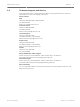
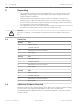
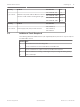
Table Of Contents
- Title Page
- Table of Contents
- Safety
- Unpacking
- Product Description
- Electrical Connections
- Install the MIC (standard) PSU
- MIC PSU Overview
- About the MIC Shielded Composite Cable
- Composite Cable Color-coding
- Earth Link on PCB
- Fuse Ratings
- Alarm Inputs
- Layout of MIC Power Supply Units (PSUs)
- Installation Warnings and Prerequisites
- Installation Instructions (Power Supply)
- Commissioning the Camera with Heater Option Fitted
- Simultaneous IP and Analog Video/Control ("Hybrid" Operation)
- Fit the Sunshield (MIC612)
- Getting Started
- Controlling the Camera
- On-Screen Display (OSD) Menus (Bosch Protocol)
- On-Screen Display (OSD) Menus (Pelco Protocol)
- Operation of the Thermal Camera
- Common User Commands
- Advanced Features
- Maintenance and Troubleshooting
- Technical data
- Appendices
- Back Page

Quantity Product Part Number Size
1 per camera
Shielded Composite Cable for MIC612 cameras
(See the model numbers and lengths at right.)
MIC-THERCBL-2M 2 m
MIC-THERCBL-10M 10 m
MIC-THERCBL-20M 20 m
MIC-THERCBL-20M 25 m
Quantity Product Part Number
1 per camera Power Supply Unit (PSU) for MIC cameras
MIC-240PSU-2,
MIC-115PSU-2,
MIC-24PSU-2
Additional Tools Required
The following table lists additional tools (not supplied by Bosch) that are or may be required
to install a MIC camera:
Quantity Part
1 13 mm wrench for the mounting bolts
1 3 mm screwdriver for the terminal blocks in the MIC PSU
1 8 mm screwdriver for captive screws for the MIC PSU enclosure
1 Silicone sealant for ensuring a water tight seal [if not using the Nebar gasket]
1 Roll of PTFE tape
2.3
MIC612 Thermal Camera Unpacking | en 9
Bosch Security Systems Operation Manual 2016.03 | 2.2 | F.01U.249.416