® HORIZONTAL / VERTICAL GAS LOG SPLITTER 27 / 32 / 37 TON Scan the QR code for assembling reference MODEL NO.: WD27T / 32T / 37T Owner’s Manual ASSEMBLY & OPERATING INSTRUCTIONS Purchase Date___________________ Serial NO.______________________ Dealer________________________________________________________ Boss Industrial, Inc. • 1208 N. Independence Blvd • Romeoville, IL 60446 • USA Phone: (800) 780-BOSS (2677) • Fax (331) 472-2976 www.boss-industrial.
To The Owner Thank You! Thank you for purchasing a BOSS Log Splitter. It was carefully engineered to provide excellent performance when properly operated and maintained. Please read this entire manual prior to operating the equipment. It instructs you how to safely and easily set up, operate and maintain your machine. Please be sure that you, and any other persons who will operate the machine, carefully follow the recommended safety practices at all times.
Table of Contents Page(s) Section I: Know Your Log Splitter...........................................................................................................................1-5 Log Splitter Overview.....................................................................................................................................1 Safety Decals..............................................................................................................................................
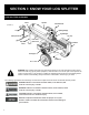
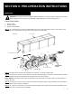
SECTION I: KNOW YOUR LOG SPLITTER LOG SPLITTER OVERVIEW Beam Cylinder Control Handle (FIGURE 1) End Plate Tongue Splitting Wedge Log Dislodger Safety Chain Log Tray Flip-down Stand Horizontal Beam Lock Gas Engine D.O.T. Tire End Plate Dipstick Reservoir DANGER! This machine was built to be operated according to the safe operation practices in this manual. As with any type of power equipment, carelessness or error on the part of the operator can result in serious injury.
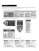
SAFETY DECALS Make sure that all safety warning decals are in good condition and readable. Always replace missing or defaced decals. Contact Boss Industrial, Inc. at 1-800-780-2677 for replacement decals. 1. Safety Warning / Operating Label (Part #: 410-188) 2. Pinch Point Warning Label (Part #: 410-233, 410-237) 3. Towing Safety Label (Part #: 410-249) 4. Oil Label (Part #: 410-647) 5. Serial NO. / Spec.
This page depicts and describes safety symbols that may appear on this product. Read, understand, and follow all instructions on the machine before attempting to assemble and operate. Symbol Description READ THE OPERATOR’S MANUAL(S) Read, understand, and follow all instructions in the manual(s) before attempting to assemble and operate. FACE PROTECTION Always wear safety goggles or safety glasses with side shields, or a face shield when operating this product as well as ear protection.
IMPORTANT TIPS 1. DO NOT discard packing materials until you have carefully inspected and satisfactorily operated the tool. 2. Read, understand, and follow all instructions on the machine and in this manual and the engine manual before attempting to assemble and operate. Keep the manuals in a safe place for future and regular reference and for ordering replacement parts. 3. Lubricate the wedge and upper side of the machine body for splitting smoothly. See FIGURE 1 4.
FIRE PREVENTION Gasoline is a highly flammable liquid and the vapors are explosive. To avoid personal injury or property damage, use extreme care in handling gasoline. Always follow these precautions below, and refer to the Engine Manual for more safety instructions. 1. ALWAYS take a Class B fire extinguisher with you when operating this log splitter in dry areas. 2. NEVER operate your log splitter near a flame or spark or smoke during operation.
SECTION II: PRE-OPERATION INSTRUCTIONS UNPACKING GENERAL REPAIR WARNING! This product has been shipped partially assembled. Use extreme caution unpacking this machine. Some components are very heavy and will require additional people or mechanical lifting tools. Unpacking tools needed: 1. Wrench 13mm 2. Scissors or knife 3.
NOTE: Due to the weight / size of the two assemblies, it’s recommended two or more adults to assist lifting and moving them. Lifting tools such as hoist, crane, jack, etc. are also recommended. Step 6: Inspect if all component assemblies, parts and accessories are included as listed in the Packing List (Page 27). If any parts are damaged or missing, please call our customer service department at 1-800-780-2677 or send an email to service@boss-industrial.com for assistance.
STEP 2: Install the two wheels. See FIGURE 6 1. The wheel axels are attached on two wheels at the manufacturer’s. Insert the wheel axels through the axle bracket tubes underneath the reservoir. 2. Screw the bore nuts onto the axels and tighten with an adjustable wrench. Align the holes of the nut and the axels. 3. Insert the split pin into the aligned holes axel, and then bend the ends of the pin with needle nose pliers. (FIGURE 6) REF. NO. DECSRIPTION 4 5 D.O.T.
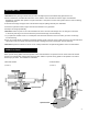
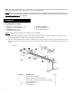
REF. NO. DECSRIPTION 9 10 Engine / Pump assembly Hardware kit # 5-1 (27 / 32T) Hex head bolt / M8 x 40 (27 / 32T) Flat washer / M8 (27 / 32T) Lock nut / M8 (27 / 32T) Vibration isolator / Ø9 (27 / 32T) O Seal ring / Ø15*1.9 10-1 10-2 10-3 10-4 // QTY. or # 5-2 (37T), including: or M10 x 40 (37T) or M10 (37T) or M10 (37T) or Ø11 (37T) 1 1 4 8 4 4 2 STEP 4: Install the beam assembly. See FIGURE 8. 1. Stand the beam upright on a flat level.
STEP 5: Attach the hoses. See FIGURE 9. 1. Oil suction hose Ø24, is included in the hardware kit box, labeled as ① Loosen the hose clamps on both ends using a flat head screwdriver, and then connect one end of the hose to the fitting at the bottom of the pump, the other end to the bottom fitting on the reservoir. Tighten the hose clamps. 2. Pump / Valve connecting hose 1/2” labeled as ②, comes from the bottom of the valve on the beam assembly.
STEP 6: Install the log tray assemblies and the manual container to the beam. See FIGURE 10. 1. Lower the beam to horizontal position. Please refer to “Beam Operating Positions” section in Page 13. 2. Position the log tray frames onto the beam as shown below and secures with the M10 hardware loosely. 3. Tighten the M10 hardware using an 16mm wrench on the bolts, and a 17mm wrench on the lock nuts. 4. Attach the manual container to the beam with the M6 hardware using a cross head screwdriver.
(FIGURE11) STEP 9: Fill hydraulic oil. See FIGURE 12. The log splitter is shipped without hydraulic fluid in the reservoir. You must fill the reservoir before your initial use. 1. Please select the oil based on the outside temperature range the log splitter will be used in. Refer to the chart provided to select the appropriate hydraulic oil. The machine was tested by the manufacturer using AW32 oil, so that AW32 oil is highly recommended for most users in most areas. The reservoir tank has a capacity of 3.
4. Start the engine and use the control handle to engage the wedge to the farthest extended position and then retract fully. Repeat this operation for 12 cycles to repel the air trapped in the hydraulic system. Much of the fluid will be drawn into the cylinder and hoses. Stop the engine, and check the oil level as instructed below. NOTE: Make sure the oil level is above the bottom line on the dipstick. If not, refill the reservoir to prevent damage to the hydraulic pump. DO NOT overfill.
2. To place the beam in the Horizontal Position proceeds as follows: 1) Pivot the beam to the horizontal position. 2) The horizontal beam lock is self-locking. The spring loaded lock will snap into place when the beam is lowered into position. ● Check all nuts, bolts and hydraulic fittings are tight to be sure the equipment is in a safe working condition. ● Adjust handle release lever. Your log splitter is equipped with an external pressure release system which is attached under the valve bracket.
SECTION III: OPERATION INSTRUCTIONS • Start the engine as the instructions in the Engine Operator’s manual packed with your log splitter. • Grab the log on the sides and place it firmly on top of the beam against the end plate to split the wood in the direction of the grain. See FIGURE 16. • Use your right hand to push the control handle lever to the Forward position to split the wood. See FIGURE 16. The control handle has three positions. See FIGURE 15.
• Remove partially split wood from wedge. 1) If the log is clipped or jammed on the wedge, release the control handle and shut off the engine immediately. Gently knock off the log with a hammer or mallet (not with your hands). WARNING! Never remove partially split wood from the wedge with your hands. Fingers may become trapped between the split wood. 2) Once removed from the wedge, split the wood from the opposite end or in another location.
SECTION IV: MAINTENANCE OFF SEASON STORAGE If the log splitter will not be used for more than 30 days, prepare it for storage as follows: • Refer to the Engine Operator’s manual packed with your log splitter for information on the off-season storage of the engine. • Store unit in a clean, dry area. Do not store it next to corrosive materials, such as fertilizer. • Clean the log splitter thoroughly. Wipe the machine with an oiled rag to prevent rust, especially on the wedge and the beam. NOTES 1.
(FIGURE17) Spring Clip Locking Pin Latch Assembly Hitch Coupler Safety Chain NOTES 1. NEVER exceed 45 mph when towing your log splitter. Towing the log splitter at speeds higher than 45 mph could result in loss of control, damage to the equipment, or serious injury or death. 2. NEVER carry any cargo or wood on your log splitter. 3. NEVER allow anyone to sit or ride on your log splitter. 4. ALWAYS turn the engine to the “OFF” position before towing the log splitter.
MAINTENANCE & ADJUSTMENTS Regular maintenance is the way to ensure the best performance and long life of your machine. • Refer to the Engine Operator’s manual packed with your log splitter for all engine maintenance e.g. how to check and change the engine oil. • Do not make any adjustments without first stopping the engine, disconnecting the spark plug wire and grounding it against the engine. Always wear safety glasses during operation or while performing any adjustments or repairs.
TROUBLESHOOTING Most problems are easy to fix. Consult the trouble shooting Table below for common problems and their solutions. An unusual noise or vibration is generally a warning of trouble. Check for damaged parts and clean, repairs and / or replace as necessary. If you continue to experience problems, contact us at www.boss-industrial.com, send an email to service@boss-industrial.com, or call toll-free (800) 780 2677 for support.
TECHNICAL SPECIFICATIONS Model WD27T Engine B&S, CR950 Pump WD32T B&S, XR1150 WD37T B&S, XR1450 Two-Stage, 9 gpm Two-Stage, 13 gpm Two-Stage, 16 gpm Cylinder (Bore x Stroke) 4 in. x 22.6 in. 4.5 in. x 22.6 in. 5 in. x 22.6 in. Maximum Splitting Force 27 Tons* 32 Tons* 37 Tons* Hydraulic Pressure 4050 psi* 3950 psi* 3800 psi* 25 in. 25 in. 25 in. 7 in. 8 in. 8 in. Forward 8 Seconds* 7.5 Seconds* 7.5 Seconds* Reverse 7 Seconds* 7 Seconds* 7 Seconds* D.O.T. 16 x 4.
EXPLODED DIAGRAM & PARTS LIST Page 25 22
REF # 1 SPECIFICATIONS 310-658 Beam incl. End Plate 25 Ton 10-10-10 310-346 Beam incl. End Plate 30 Ton 10-12-10 310-471 Beam incl. End Plate 35 Ton 12-12-12 QTY PER UNIT 1 530-421 Splitting Wedge w/ Guides 25 Ton Guide12, 7” 530-422 Splitting Wedge w/ Guides 30 Ton Guide12, 8” 530-423 Splitting Wedge w/ Guides 35 Ton Guide14, 8” 3 760-118 Pin PH, Ø16*69-Ø4.5 1 4.1 750-566 Flat Washer PH, M16 2 4.2 760-734 Split Pin ZP, Ø4*35 2 530-468 Cylinder 25 Ton 4.0 in. * 22.6in.
REF # PART # PART NAME SPECIFICATIONS QTY PER UNIT 32 750-834 Spring Washer ZP, M8 4 33 710-632 Hex Head Bolt ZP, 5/16-24*20 4 34 750-617 Flat Washer ZP, 5/16 4 35 750-844 Spring Washer ZP, 5/16 4 770-123 Engine Shaft Square Key 3/16 X 1.75 (27 / 32T) 770-125 Engine Shaft Square Key 1/4 X 2.165 (37T) CR950 Gas Engine (B&S 6.5) 25T XR1150 Gas Engine (B&S 8.0) 30T XR1450 Gas Engine (B&S 10.
REF # PART # PART NAME SPECIFICATIONS 86 720-536 Lock Nut ZP, M12 2 87 320-942 Log Tray Plate WD 2 88 320-940 Log Tray Frame (FR, BL) WD 2 89 320-948 Log Tray Frame (FL, BR) WD 2 90 720-120 Lock Nut ZP, M10 4 91 750-525 Flat Washer ZP, M10 8 92 710-556 Hex Head Bolt ZP, M10*45 4 93 710-520 Hex Head Bolt ZP, M10*25 8 94 750-525 Flat Washer ZP, M10 16 95 720-120 Lock Nut ZP, M10 8 96 320-926 Log Dislodger (L) 97 320-927 Log Dislodger (R) 98 710-438
WARRANTY LIMITED WARRANTY STATEMENT Boss Industrial, Inc., (“Boss Industrial”) warrants to the original retail purchaser that this BOSS brand outdoor product is designed and made to the highest line standards applicable and agrees to repair or replace, at Boss Industrial’s, discretion, any defective product in material and workmanship free of charge within these time periods from the date of purchase under the limited warranty terms below.
PACKING LIST Beam asembly x 1 Page 30 27 Engine-Pump x 1 Tongue assembly x 1 Hardware kits box x 1, including: Reservoir tank assembly x 1 Hardware kit # 2-1, 5, 6-1, 6-2 Log tray & Log dislodger assembly x 2 Engine manual x 1 Wheel assembly x 2 Oil suction hose x 1 Manual container x 1 Instruction manual x 1
Page 31
Boss Industrial, Inc. • 1208 N. Independence Blvd. • Romeoville, IL 60446 • USA Phone: (800) 780-BOSS (2677) • Fax (331) 472-2976 www.boss-industrial.