Page 1 of 67 Installation & Maintenance Manual For Camray 5 and Camray Utility 5 Oil Fired Boilers Manual Part No. PL 47000 Issue No. 4 Date of Issue: November 2001 file://D:\PL47000\PL47000.
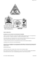
Page 2 of 67 HEALTH AND SAFETY INFORMATION FOR THE INSTALLER AND SERVICE ENGINEER. Under the Consumer Protection Act 1987 and the Health and Safety at Work Act 1974, it is a requirement to provide information on substances hazardous to health (COSHH Regulations 1988). The Company takes every reasonable care to ensure that these products are designed and constructed to meet these general safety requirements, when properly used and installed.
Page 3 of 67 After handling wash hands and other exposed parts. When disposing, reduce dust with water spray, ensure parts are securely wrapped. GLUES, SEALANTS & PAINT Glues, Sealants and Paint are used in the product and present no known hazards when used in the manner for which they are intended. Kerosene & GAS OIL FUELS (MINERAL OILS) 1. The effect of mineral oils on the skin vary according to the duration of exposure. 2.
Page 4 of 67 1:5:7 Shutting Off for Summer 1:5:8 Sealed System Central Heating 1:5:9 Frost Protection 1:5:10 Oil Delivery 1:5:11 Maintenance/Troubleshooting Guide 1:5:12 Option Programmer SECTION 2 - INTRODUCTION 2:1 Introduction 2:2 Flue Options 2:3 Commissioning 2:4 Safety SECTION 3 - TECHNICAL DATA 3:1 Fuels 3:2 Boiler Technical Details 3:3 Burner Details 3:4 Electric’s 3:5 Dimensions 3:6 Commissioning Data SECTION 4 - INSTALLATION 4:1 Standards and Regulations 4:2 The Heating System 4:3 Siting & Positi
Page 5 of 67 7:4 Recommended Commissioning Check List 7:5 Recommended Commissioning Tests SECTION 8 - MAINTENANCE 8:1 Maintenance 8:2 Air Shutter Adjustment 8:3 Baffle Arrangement SECTION 9 - SPARES & ACCESSORIES See Spare Parts SECTION 10 - FAULT FINDING 10:1 Fault Finding 10:2 Fault Finding Chart BOULTER BUDERUS CAMRAY 5 PAGE 1 1:1 INTRODUCTION Getting to Know your New Camray 5 Boiler Thank you for choosing the Camray 5 -manufactured in the UK by Boulter Buderus who are renowned oil-firing specialists.
Page 6 of 67 Oil Tank Capacity Oil Supplier 1 Litres Oil Supplier 2 1:2 IMPORTANT SAFETY NOTES To obtain the best possible performance and trouble free operation from your Boiler, it is important that you read these instructions carefully. Your Camray Boiler has built-in safety features, which are detailed in the relevant section of this manual. 1:2.1 The heating system must comply with the latest editions of British Standard 5410 and The Building Regulations.
Page 7 of 67 1:4 BOILER CONTROL PANEL Boiler Control Panel (see fig 1) 1. Boiler Control Thermostat Switch/Mains On Switch. 2. Boiler Overheat/Limit Thermostat Reset Button. 3. ‘Lockout’ Indicator- RED. }These will not be lit until activated 4. Mains Indicator- ORANGE 5. Limit Indicator - RED. }These will not be lit until activated }These will not be lit until activated 6. Burner on Indication - ORANGE. 1:5 OPERATING INSTRUCTIONS 1:5.
Page 8 of 67 Control Panel Arrangement BOULTER BUDERUS CAMRAY 5 PAGE 3 1:5.4 LOCKOUT INDICATOR (Camray 5 Kitchen Model Only) In the unlikely event of a Burner malfunction, it will automatically shutdown, and the red lockout indicator on the Control Panel will be lit. To restart the Burner, wait for a period of at least 45 seconds. Remove the front door panel (as illustrated) and press the lockout reset button located on the front of the Burner (see fig 2).
Page 9 of 67 1:5.5 STARTING THE BOILER 1. Ensure that all external controls, e.g. programmer, timer, room thermostat etc., are turned on and calling for heat. 2. Make sure the Boiler Control Thermostat is set within the recommended range (see fig 1) and that the mains electricity and oil are turned on. 1:5.
Page 10 of 67 Please also note that on conventional flue models, it is possible for the air intake at the rear of the Boiler casing to become blocked with household debris. This air intake must remain clear at all times and so it is advisable to inspect and clean this area regularly. Please refer to section 1:2.2 in this booklet.
Page 11 of 67 3. Suitable for sealed Central Heating systems which are within the maximum permitted working pressure. All Boilers are supplied with a manual reset limit thermostat. 4. Suitable for new installations and for replacing existing boilers. CAMRAY Boilers offer greater freedom to select the most suitable position for siting and the opportunity to install the boiler in a suitable outbuilding if required.
Page 12 of 67 2:4 SAFETY READ HEALTH AND SAFETY INFORMATION ON INSIDE FRONT COVER OF THIS MANUAL. IMPORTANT Should you wish to remove or dismantle any covers or parts of the boiler for cleaning or maintenance ALWAYS FIRST SWITCH OFF THE ELECTRICITY SUPPLY. 1. On no account should any part of the Boiler or its Flue be modified with the exception of flues which require adjusting to length to suit site conditions, as detailed in this manual. 2.
Page 13 of 67 Electrical Supply 230v., 1 Ph., 50Hz. IMPORTANT The Electrical Installation of this appliance must be performed by a suitably qualified electrical engineer/installer. All wiring to supply and all system components external to boiler must comply with the latest edition of BS7671:1992 formerly IEE Wiring Regulations. This appliance must be effectively earthed and connection to the supply must be through a double pole isolating switch fused 5 amp.
Page 14 of 67 BOULTER BUDERUS CAMRAY 5 PAGE 8 3:6 COMMISSIONING DATA 3:6.1 Class C2, Kerosene Oil RIELLO BURNER Model Camray5 Utility & System 40/65 65/90A 95/130A Output Riello RDB TYPE kW Btu/h x1000 Nozzle Danfoss Delevan US/GPH Pump Fuel C02% Smoke Flue Exit Pressure Rate No. Temp oC Kg/h Gross BAR psi Boiler Test Point Temp oC 11.7 40 0.4x60oES 7.0 100 1.08 10 0-1 165-195 215-245 16.1 55 484T50 0.5x60oES 8.0 115 1.49 11 0-1 180-225 260-285 19 65 0.6x60oES 7.6 110 1.
Page 15 of 67 Heat Input (Full Load) kW (based on Net efficiency of 91%) Heat Output (Full Load) kW 22.1 29.0 41.9 19 26.4 38.1 BOULTER BUDERUS CAMRAY 5 PAGE 9 4:1 STANDARDS & REGULATIONS The installation of the Boiler must comply with the latest edition of : BS 5410 Oil Installations Pt 1 up to 44kW; Pt 2 and over 44kW BS 5449 Forced circulation hot water central heating systems for domestic premises. BS 4543 Pt. 1 & 3 Factory made insulated chimneys.
Page 16 of 67 Consideration must be given however, to the following points. 1. Noise may be accentuated by the installation in small rooms or recesses with hard or hollow stud wall surfaces. Due consideration to the siting of boilers should be given. Further advice from BOULTER BUDERUS should be sought where any doubt exists. 2. Some individuals may be particularly sensitive to even low noise levels and this should be discussed before installation. 3.
Page 17 of 67 The boiler requires a minimum stable draught of 0.1 mbar (0.04w.g.). If the chimney exceeds 6m (20 feet) in length, it may produce a draught exceeding 0.37 mbar (0.15" w.g.) and a draught stabiliser should be fitted. The chimney should comply with the latest edition of the Building Regulations and BS 5410: Part 1. Factory built chimneys must comply with the Building Regulations and BS 4543 Parts 1 and 3.
Page 18 of 67 This air enters the Boiler through the back panel. At least 15mm clearance is required at the rear of all boilers. When the boiler is situated in a confined space or chamber a permanent adequate supply of air is required for ventilation to prevent over heating. 4:6.
Page 19 of 67 coloured green. Plastic tanks do not need to stand on piers, but should be supported across the entire base area, ideally on 50mm thick garden slabs or a concrete base. As there is only one tapped outlet they are more suited to single pipe feed as gravity supply or with a Boulter 3K Oil Loop Deaerator where suction lift is required. (Part No. BS 03060) 4:8 OIL SUPPLY The oil entry holes in the boiler casing are shown in the diagram in Section 3:5 of this manual.
Page 20 of 67 4:8.4 Two Pipe System Fig. 4:8d When the bottom of the Oil Tank is below the level of the Oil Pump on the Burner it is necessary to install an additional 10mm return pipe. The Oil Filter, Shut Off Valve, spring loaded Non-Return Valve and Fire Check Valve are always in the suction line supplying oil from the Tank to the Burner. The Non-Return Valve must be fitted to allow the BOULTER BUDERUS CAMRAY 5 PAGE 12 flow in the correct direction and prevent drain back to the Tank, see fig. 4:8e.
Page 21 of 67 Flexible Oil Pipes and Fire Check Valve BOULTER BUDERUS CAMRAY 5 PAGE 13 file://D:\PL47000\PL47000.
Page 22 of 67 BOULTER BUDERUS CAMRAY 5 PAGE 14 file://D:\PL47000\PL47000.
Page 23 of 67 BOULTER BUDERUS CAMRAY 5 PAGE 15 file://D:\PL47000\PL47000.
Page 24 of 67 BOULTER BUDERUS CAMRAY 5 PAGE 16 4:9 OIL BURNER The Burner makers’ technical leaflet is supplied with this manual and provides supplementary information not included in this manual. 4:9.1 Burner Pump for Two Pipe and Deaerator System For two pipe oil systems the Burner Oil Pump has to be fitted with the Bypass Screw supplied. Boilers are despatched with the Bypass Screw in a labelled envelope attached to the Burner. This socket screw is inserted into the return port as shown in Fig. 4:9a.
Page 25 of 67 4:9.2 Burner Pump for Single Pipe System The burner is supplied set for single pipe operation. The return port is plugged and the Bypass Screw is not fitted. See Fig. 4:9b. BOULTER BUDERUS CAMRAY 5 PAGE 17 4:10 CONTROL PANEL The Control Panel is pre-wired and fitted to the Boiler ready for connection to the system wiring. 4:10.1 Connecting Control Panel If a Boulter Programmer is to be fitted refer to section 4:11 of this manual for fitting instructions before connecting mains. 1.
Page 26 of 67 2. Insert Mains Plug into the mating Mains Socket on the underside of the Control Panel. 3. Insert 4 pin Burner Plug on the end of the Burner Cable into its mating Socket on the underside of the Control Panel. See Fig. 4:10a. NOTE: The 4 pin plug has an engagement peg. Depressing the peg with a small screwdriver allows the release of the plug from the socket. 4:10.2 Phial Positions 1.
Page 27 of 67 BOULTER BUDERUS CAMRAY 5 PAGE 18 4:11 PROGRAMMER - CAMRAY 5 ONLY IMPORTANT The Electrical Installation of the programmer must be carried out by a suitably qualified electrical engineer/installer The Programmer kit is available as an optional extra. ( FOR THE WHITE CASED KITCHEN MODEL ONLY) The unit is supplied pre-wired to a 12-way Terminal block as detailed in the wiring diagram and is available as Kit Part No.
Page 28 of 67 4. Remove the plate and carefully cut through the overlay with a sharp knife. 5. Feed the pre-wired terminal block and wires through the hole now exposed in the Control Panel. Click the Programmer in place from the front. 6. Screw the terminal block and Legend Plate to the support bracket the LEN going uppermost. Wiring Programmer 1. Remove Red Wire (F) from Limit Thermostat Terminal (G) and 3 way Terminal block (H) and discard. 2. Fit Brown Wire (J) spade onto vacated Terminal (G). 3.
Page 29 of 67 BOULTER BUDERUS CAMRAY 5 PAGE 19 PROGRAMMER INSTRUCTIONS 4:11.1 INTRODUCTION The Boulter Programmer is available in kit form as an optional extra for Boulter Buderus. Fitting Instructions for the programmer are included in the Programmer Kit. The Timer/Programmer is supplied pre-programmed with a ‘Standard’ set of times. These may be as required but can be easily changed if not. See 4.11.6 for Standard Time Settings. 4:11.
Page 30 of 67 4:11:4 SETTING THE CLOCK 1. Switch ON the Electrical Supply to the Boiler - the Clock Display should come on. 2. Press and release once. Display > 3. Press and release once to answer. The Day on the Display will flash. Display > 4. Use or to select Day. 5. Press and release once. 6. The Hour on the display will flash. Display > Use the or to change Hour. The Clock is a 12 hour display - check the AM and PM. 7. Press and release the once. 8.
Page 31 of 67 1. If no button is pressed for 1 to 2 minutes during programming, the unit will revert to normal operating mode. 2. The + and - buttons are used to change times. Press and release for small changes. Press and hold to skit through quickly. 3. The 6 switching times ON1 OFF1, ON2 OFF2, ON3 OFF3 must be in time order. The unit will not accept times if they are not correct. 4. The first switching time ON1 must be set after 12:00am (Mid-night). 5.
Page 32 of 67 8. OFF1 9. ON2 10. OFF2 - HW OFF - HW ON - HW OFF 20. OFF1 21. ON2 22. OFF2 - HW OFF - HW ON - HW OFF 11. ON3 12. OFF3 - HW ON - HW OFF 23. ON3 24. OFF3 - HW ON - HW OFF 4:11.8 PROGRAMMING PROCEDURE To create a programme the same method is used as for setting the Clock. With the Timer/Programmer in the operating mode and the Display showing the correct Time and Day. (Refer to section 4:11.
Page 33 of 67 Press three times. Display > Press - then press and hold and the display will ‘run’ and pause for 2-3 seconds on the first ON time of the day you are at. The On indicator lights will illuminate and heating/hot water circuits will be energised. Releasing the YES button will stop the display running. Continue pressing Press button to run through the 7 days of the programme pausing at each switching time. twice to cancel Test and return to operating mode. 4:11.
Page 34 of 67 BOULTER BUDERUS CAMRAY 5 PAGE 22 IMPORTANT ENSURE GOOD EARTH file://D:\PL47000\PL47000.
Page 35 of 67 4:12.1 Typical External Wiring options IMPORTANT Blue tag must only be fitted to terminal 6 of time clock for gravity hot water only. It must be removed for fully pumped systems. BOULTER BUDERUS CAMRAY 5 PAGE 23 5:1 BALANCED FLUE BOILERS file://D:\PL47000\PL47000.
Page 36 of 67 A range of Balanced Flue Kits are available as optional extras for Camray 5 & Utility. Balanced Flues permit considerable choice of siting of the Boiler. Boilers may be installed in situations where no chimney exists, where the chimney is unsatisfactory or in outhouses. It is important that care is exercised in choosing a suitable location for the Boiler and Flues.
Page 37 of 67 Vertical Balanced Flues enables boilers to be installed in single storey outhouses or utility rooms where it may not be convenient for it to be sited near an outer wall. It may also be employed to exhaust vertically to avoid nearby windows or doors. Vertical Balanced Flues may also be preferred in cases where close proximity to adjoining houses or property dictates minimum exhaust noises. 5:3.
Page 38 of 67 C D E From any Internal Corner Above Ground From a surface facing the Terminal 300 300 600 F From a Terminal facing a Terminal 1200 G Vertically between Two Terminals on the same wall 1500 H J K Horizontally between Two Terminals on the same wall From any External Corner Horizontally from any Opening, Air Brick, Window or Door 750 300 600 L Vertical Flue from Wall (Flat or Pitched Roof) 750 (900) (600) (1200) (1200) (600) *Where the terminal is within 1m of any plastic materi
Page 39 of 67 5:7 BLANKING PLATES The Boiler is supplied in Balanced Flue form. With 2 full side/rear Blanking plate and one top blanking plate. The Blanking plates should be fitted to prevent access to hot surfaces and to maintain the efficiency of the boiler. BOULTER BUDERUS CAMRAY 5 PAGE 26 6:1 NOTES ON INSTALLATION LOW LEVEL AND HIGH LEVEL BALANCED FLUES 1. The Terminal must be slightly angled down to ensure correct operation of the boiler.
Page 40 of 67 acidic due to the fuel characteristics and it is advisable not to install the flue in any position where the condensation could cause damage to paint surfaces etc. 2. The Terminal index plate should be sealed to the external wall using silicon sealant or other impervious material to prevent water ingress. 3. Ensure that the outlet of the Terminal points downward (TOP upper-most and Boulter correct way up). 4.
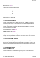
Page 41 of 67 BOULTER BUDERUS CAMRAY 5 PAGE 28 LOW LEVEL FLUE INSTALLATION Site conditions will dictate to a certain extent the best method of assembling low level balanced flues. The illustration shows a typical rear outlet flue. Assemble the flue generally as follows: 1. Position boiler check that water connections and flue proposed is according to clearances specified. file://D:\PL47000\PL47000.
Page 42 of 67 2. Mark flue position. 3. Move boiler away from the wall and using a diamond tipped core drill drill a 6" (150mm) hole, ensuring the hole is horizontal. 4. Remove rear top panel of boiler and identify flue outlet (rear, LH or RH side). Move blanking plate to appropriate position using nuts and washers. 5. Ensure flue exhaust seal is in position and in good condition, ie undamaged. Lubricate with a mild detergent. 6. Place boiler offtake gasket in position on top of boiler (foil face upwards).
Page 43 of 67 BOULTER BUDERUS CAMRAY 5 PAGE 30 file://D:\PL47000\PL47000.
Page 44 of 67 HIGH LEVEL SIDE & REAR INSTALLATION Assemble the flue generally as follows: 1. Position boiler check that all water connections and proposed flue position are according to clearances specified. 2. Mark the flue position on the wall. 3. Move the boiler away from the wall and using a diamond tipped core drill drill a 6" 150mm hole in the wall ensuring the hole is level. 4.
Page 45 of 67 10. Take High Level elbow fit larger O Ring seal to short arm, lubricate with a mild detergent and ensure flue exhaust seal is fitted to the inner duct undamaged and in the correct orientation. 11. Ensuring there is no debris in the wall place longer arm through drilled hole and slide into second extension being careful not to scratch metal work. The high level elbow must be slightly sloped downwards. 12.
Page 46 of 67 BOULTER BUDERUS CAMRAY 5 PAGE 32 6:4 VERTICAL FLUE FLAT ROOF INSTALLATION file://D:\PL47000\PL47000.
Page 47 of 67 BOULTER BUDERUS CAMRAY 5 PAGE 33 6:4 VERTICAL FLUE FLAT ROOF INSTALLATION - CONTINUED 6:4.1 Notes on installation file://D:\PL47000\PL47000.
Page 48 of 67 Site conditions will dictate the best method of assembling the Vertical Balanced Flue. The following illustrations show boilers up against a rear wall as an example. It is not essential for the boiler to be positioned this way; As long as the joists are capable of supporting the flue via the support plate supplied in the kit. The Vertical Flue is telescopic to allow for various ceiling heights. (See attached colour leaflet).
Page 49 of 67 12. Fit the vertical flue offtake plate to the rear top panel of the boiler and fit the assembly into position over the vertical offtake spigot. 13. Take one of the 500mm vertical extensions or 1000mm, fit an O Ring Seal to the outer duct, and ensure that the flue exhaust seal is fitted to the inner ducts undamaged and in the correct orientation. Lubricate all seals with a mild detergent. 14. With the seals fitted slide the extension in to the offtake socket external O Ring end first. 15.
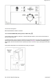
Page 50 of 67 Fig. 6:4b Vertical Flue - Flat Roof Assembly BOULTER BUDERUS CAMRAY 5 PAGE 35 6:5 VERTICAL FLUE PITCHED ROOF INSTALLATION file://D:\PL47000\PL47000.
Page 51 of 67 BOULTER BOILERS CAMRAY 5 PAGE 36 6:5 VERTICAL FLUE PITCHED ROOF INSTALLATION - CONTINUED 6:5.1 Notes on installation file://D:\PL47000\PL47000.
Page 52 of 67 Site conditions will dictate the best method of assembling the Vertical Balanced Flue. The following illustrations show boilers up against a rear wall as an example. It is not essential for the boiler to be positioned this way. As long as the joists are capable of supporting the flue via the support plate supplied in the Kit or the Flue support quadrant kit (optional). The vertical flue kit is telescopic to allow for various ceiling heights.
Page 53 of 67 12. Take the extension, fit O Ring seals to the outer duct and ensure that the flue exhaust seal is fitted to inner ducts undamaged and in the correct orientation. Lubricate all seals with a mild detergent. 13. With both seals fitted slide the 1st extension into position. 14. Add extensions until the joint nearest the ceiling is 150mm away. Slide the ceiling trim onto this last extension ensuring it is the correct way up (screws at the top). 15.
Page 54 of 67 Fig. 6:5b Vertical Flue - Pitched Roof Assembly BOULTER BUDERUS CAMRAY 5 PAGE 38 6:6 HIGH LEVEL FLUE LENGTH ALTERATION There is a certain amount of adjustment available on the vertical height and horizontal length. This is attained by pushing two telescopic flues together until the desired dimension is obtained. Secure any vertical lengths by using a drill and 4 self tapping screws supplied. BOULTER BUDERUS CAMRAY 5 PAGE 39 7:1 COMMISSIONING file://D:\PL47000\PL47000.
Page 55 of 67 It is essential in the interest of boiler efficiency and reliable performance that once the boiler has been installed it is first commissioned by a competent engineer, preferably an OFTEC commissioning engineer. If an engineer is not known Boulter Boilers will be pleased to provide details of commissioning and servicing engineers from their register. Commissioning must be carried out at the point of first firing. Incorrect emissions can cause premature fouling of the flue ways.
Page 56 of 67 Contents gauges Screw fill and indepentant vent cover or capped fill and vent pipes. Outer valve Filter Sludge cock (Non plastic tanks). HEIGHT OF TANK Is the bottom of the tank above the oil pump if a single pipe system is installed? OIL SUPPLY LINE Ensure that galvanised iron has not been used. If black iron has been used, is it protected against corrosion? Ensure that soldered connections on copper pipes have not been used.
Page 57 of 67 IF NOT THIS MAY DAMAGE THE PUMP. Clear oil filters and de-sludge the tank if necessary. TWO PIPE OIL SYSTEMS Is a spring-loaded non-return oil valve fitted in the suction line? (or a 3K Oil Deaerator).
Page 58 of 67 Is the flue adequately sized for the appliance rating? Is the flue free of any obstruction? Has the chimney been adequately lined and insulated? NOTE:- Lining the flue and back filling will help prevent condensate problems BALANCED FLUE APPLIANCES Is the correct flue kit fitted? Is the Flue off take correctly secured to the boiler by four nuts and washers.
Page 59 of 67 Does the power supply cable enter the casing through a grommet? GENERAL Has the boiler been installed in accorandance with manufacturers instructions? BOULTER BUDERUS CAMRAY 5 PAGE 42 7:5 BOULTER BUDERUS RECOMMENDED COMMISSIONING TESTS Have the manufacturers on-site assembly instructions been followed? COMMISSIONING TESTS BEFORE ATTEMPTING TO START THE BOILER PLEASE THOROUGHLY CHECK ALL ITEMS ON THE COMMISSIONING CHECK LIST.
Page 60 of 67 Adjust the air shutter if necessary, open to reduce CO2, close to increase CO2. If the air shutter is adjusted, re-check the Smoke No. Check the flue gas temperature. The figures should agree with the Boiler Commissioning Data. Check lockout function, either cover the photocell or remove solenoid coil, to simulate flame failure. Reinstate components and press lockout button.
Page 61 of 67 Remove burner and clean thoroughly, the burner draught tube, the electrodes and generally the head assembly. CHANGE the nozzle for one with the specified make, oil rate, spray pattern and angle. Inspect the ignition electrodes for crazing in the porcelain. Replace if there are signs of deterioration. A dirty fan impeller can impair the performance of a burner, inspect and clean if necessary. Inspect photocell, if badly discoloured, change it.
Page 62 of 67 BOULTER BUDERUS CAMRAY 5 PAGE 44 8:2 AIR SHUTTER ADJUSTMENT The Burner has a fixed Air Shutter with manual adjustment. To adjust the CO2 at the Air Shutter use a 3mm allen key as shown. To increase the setting turn the airshutter clockwise (+) and to decrease turn anticlockwise (-). Fig. 8:2a Air Shutter Adjustment 8:3 BAFFLE ARRANGEMENT file://D:\PL47000\PL47000.
Page 63 of 67 Fig. 8.3a Baffle Arrangement To ensure correct placement of baffles ensure that castellated edges are positioned towards the heat exchanger and: 1. All baffles are horizontal 2. All baffle handles are in the forward position. BOULTER BUDERUS CAMRAY 5 PAGE 45 10:1 FAULT FINDING If the Boiler fails to start, make the following checks before calling a service engineer:1. Is there sufficient fuel in the storage tank? 2.
Page 64 of 67 4. Is the programmer (or Boiler Operating Switch) set to call for heat? 5. Is the Boiler Thermostat set to the desired temperature? 6. Is the Lock-out Reset Button on the Control Box and Control Panel Neon illuminated? If so, press to reset Burner. 7. Check the fuse which should have been fitted to the mains electricity supply to the programmer/boiler operating switch. If the fuse has blown, replace it. If it blows again, call a Service Engineer.
Page 65 of 67 joints or defective gland packings) Motor not driving pump shaft Blocked atomiser nozzle Oil pressure abnormally low Solenoid valve faulty 5. Burner lights up, runs continuously and emits visible smoke or shows excess smoke on combustion check 6. Burner lights up, runs normally but flame cuts off slowly on shut down (possibly with smoke or pulsation) 7. Burner Pulsates (a) continuously Check that flexible drive is functioning correctly and not slipping. Remove and replace nozzle.
Page 66 of 67 if necessary. Check by hand and replace if necessary. Replace motor. 10. 11. Motor seized Breakdown of insulation of motor windings Burner runs normally but Oil throughput Check nozzle size and pressure against rating will not reach desired insufficient temperature Boiler has become Check with heating installer. undersized due to heating system expansion Low efficiency and CO2 Check combustion readings, reset air.
Page 67 of 67 Boulter Boilers Limited Magnet House 3 0 White House Road Ipswich IP1 5JA Tel: 01473 241555 Fax: 01473 241321 E-mail: sales@boulter-boilers.com Due to a policy of continual development Boulter Boilers reserves the right to alter or amend the design of its products without prior notlce file://D:\PL47000\PL47000.