
Datasheet


Specifications are subject to change without notice.
Customers should verify actual device performance in their specific applications.
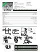
CM45, CM32, CM25, CM20, CM16, CM10 SMT Chip Inductors
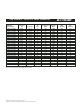
Packaging Specifications
Packaging
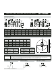
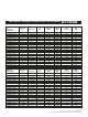
Reel Dimensions
Model A B W F E P1 P2 P3 ¿D0 ¿D1 t1 t2
CM10 0.71 (.027) 1.21 (.047) 8.00 (.315) 3.50 (.138) 1.75 (.069) 4.00 (.157) 2.00 (.079) 4.00 (.157) 1.50 (.059) 0.60 (.024) 0.27 (.011) 1.20 (.047)
CM16 1.00 (.039) 1.80 (.071) 8.00 (.315) 3.50 (.138) 1.75 (.069) 4.00 (.157) 2.00 (.079) 4.00 (.157) 1.50 (.059) 0.60 (.024) 0.27 (.011) 1.20 (.047)
CM20 1.45 (.057) 2.25 (.089) 8.00 (.315) 3.50 (.138) 1.75 (.069) 4.00 (.157) 2.00 (.079) 4.00 (.157) 1.50 (.059) 1.00 (.039) 0.25 (.010) 1.55 (.061)
CM25 2.40 (.094) 2.90 (.114) 8.00 (.315) 3.50 (.138) 1.75 (.069) 4.00 (.157) 2.00 (.079) 4.00 (.157) 1.50 (.059) 1.10 (.043) 0.25 (.010) 1.85 (.073)
CM32 2.80 (.110) 3.60 (.142) 8.00 (.315) 3.50 (.138) 1.75 (.069) 4.00 (.157) 2.00 (.079) 4.00 (.157) 1.50 (.059) — 0.25 (.010) 2.40 (.094)
CM45 3.60 (.142) 4.90 (.193) 12.00 (.472) 5.50 (.217) 1.75 (.069) 8.00 (.315) 2.00 (.079) 4.00 (.157) 1.50 (.059) — 0.30 (.012) 3.50 (.138)
CM10, CM16, CM20, CM25, CM32
CM45
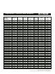
Model A B C D E W
CM10 178 (7.008) 60 min. 13 (.512) 21 (.827) 2 (.079) 9 (.354)
CM16 178 (7.008) 60 min. 13 (.512) 21 (.827) 2 (.079) 9 (.354)
CM20 178 (7.008) 60 min. 13 (.512) 21 (.827) 2 (.079) 9 (.354)
CM25 178 (7.008) 60 min. 13 (.512) 21 (.827) 2 (.079) 9 (.354)
CM32 178 (7.008) 60 min. 13 (.512) 21 (.827) 2 (.079) 9 (.354)
CM45 178 (7.008) 60 min. 13 (.512) 21 (.827) 2 (.079) 13 (.512)
Model Quantity Weight
CM10 10000 pcs 150 g
CM16 3000 pcs 90 g
CM20 3000 pcs 90 g
Model Quantity Weight
CM25 2000 pcs 100 g
CM32 2000 pcs 190 g
CM45 500 pcs 100 g
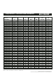
Soldering
Flow Soldering Infrared Soldering Vapor-phase Soldering
Flow Soldering 260 °C maximum for 5 seconds (2 wave solder method)
Infrared 200 °C for a maximum of 30 seconds. Peak of 240 °C for a maximum of 5 seconds.
If the solder does not reflow simultaneously under each terminal, there may be a misalignment of the component on the
board. For this reason, it is recommended that the inductor be adhered to the board prior to reflow.
Vapor-phase 215 °C for a maximum of 30 seconds.
10 seconds max.
260 °C
Preheat:
100 to 150 °C
2 minutes
min.
Preheat:
100 to 150 °C
2 minutes
min.
10 seconds max.
230 °C
200 °C
30 seconds max.
Preheat:
100 to 150 °C
2 minutes
min.
10 seconds max.
220 °C
215 °C
30 seconds max.
B
A
W
D
C
E
P1
P2
P3
A
D1
DIA.
B
ØDo
W
F
E
t2
t1
Tape running direction
Chip
Component
P1
P2
P3
A
B
ØDo
W
F
E
t2
t1
Chip
Component
Tape running direction