
Datasheet
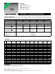

Chip Dimensions
Dimension
Model Model Model Model Model
CRL0603 CRL0805 CRL1206 CRL2010 CRL2512
L
1.60 ± 0.10 2.00 ± 0.15 3.20 ± 0.15 5.00 ± 0.20 6.30 ± 0.20
(0.063 ± 0.004) (0.079 ± 0.006) (0.126 ± 0.006) (0.197 ± 0.008) (0.248 ± 0.008)
W
0.80 ± 0.10 1.25 ± 0.10 1.60 ± 0.15 2.50 ± 0.20 3.10 ± 0.20
(0.031 ± 0.004) (0.049 ± 0.004) (0.063 ± 0.006) (0.098 ± 0.008) (0.122 ± 0.008)
H
0.45 ± 0.10 0.50 ± 0.10 0.60 ± 0.10 0.60 ± 0.10 0.60 ± 0.10
(0.018 ± 0.004) (0.020 ± 0.004) (0.024 ± 0.004) (0.024 ± 0.004) (0.024 ± 0.004)
I
1
0.30 ± 0.20 0.40 ± 0.20 0.50 ± 0.25 0.60 ± 0.25 0.60 ± 0.25
(0.012 ± 0.008) (0.016 ± 0.008) (0.020 ± 0.010) (0.024 ± 0.010) (0.024 ± 0.010)
I
2
0.30 ± 0.20 0.40 ± 0.20 0.50 ± 0.25 0.60 ± 0.25 0.60 ± 0.20
(0.012 ± 0.008) (0.016 ± 0.008) (0.020 ± 0.010) (0.024 ± 0.010) (0.024 ± 0.008)
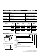
Dimensional Drawing
L
H
I
2
I
2
W
I
1
I
1
DIMENSIONS:
MM
(INCHES)
Derating Curve
100
80
60
40
20
0
Rated power in percentage (%)
-55
0
70
125
(°C) Ambient temperature
How to Order
CRL 0603 - F W - R090 E LF
Model
(CRL = Chip Resistor Low Value)
Size
• 0603
• 0805
• 1206
• 2010
• 2512
Resistance Tolerance
F = ±1 %
J = ±5 %
TCR (PPM/°C)
W = ±200 (0.05 Ω ≤ R ≤ 9.1 Ω)
V = ±400 (0.02 Ω < R <0.05 Ω)
U = ±600 (0.02 Ω)
Resistance Value (1 % or 5 %)
• R stands for decimal point. Three signifi cant digits: (R090 = 0.09 Ω; 9R10 = 9.10 Ω)
Packaging
• CRL0603, CRL0805, CRL1206: E = Paper Tape, Plastic Reel, 5,000 pcs.
• CRL2010, CRL2512: E = Embossed Plastic Tape, Plastic Reel, 4,000 pcs.
Termination
LF = Tin-plated (RoHS compliant)
3312 - 2 mm SMD Trimming Potentiometer
Specifi cations are subject to change without notice.
The device characteristics and parameters in this data sheet can and do vary in different applications and actual device performance may vary over time.
Users should verify actual device performance in their specifi c applications.
CRL Series - Low Value Chip Resistors
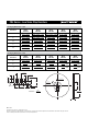
Environmental Characteristics
Description Method Limit
Short Time Overload
2.5 x (PR)
1/2
for 5 seconds. 1 % Tolerance: ΔR ≤ ±(1 % + 0.001 Ω)
(IEC 115-1 4.13) 5 % Tolerance: ΔR ≤ ±(2 % + 0.001 Ω)
Load Life
(PR)
1/2
for 1000 hours; 1.5 hours on; 0.5 hours off . 1 % Tolerance: ΔR ≤ ±(1 % + 0.001 Ω)
(IEC 115-1 4.25.1) 5 % Tolerance: ΔR ≤ ±(2 % + 0.001 Ω)
Resistance to 260 °C for 10 seconds. 1 % Tolerance: ΔR ≤ ±(0.5 % + 0.001 Ω)
Soldering Heat (IEC 115-1 4.18) 5 % Tolerance: ΔR ≤ ±(1 % + 0.001 Ω)
Thermal Shock
5 cycles from -55 °C to +125 °C, 30 minutes at temperature. 1 % Tolerance: ΔR ≤ ±(0.5 % + 0.001 Ω)
(IEC 115-1 4.19) 5 % Tolerance: ΔR ≤ ±(1 % + 0.001 Ω)