
Datasheet
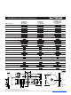

DIMENSIONS:
MM
(INCHES)
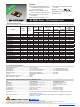
MF-MSMF Series - PTC Resettable Fuses
A
B
C
Top and Bottom View Side View
D
Top View
Style 2
Style 1
Bottom View Side View Recommended Pad Layout
8
C
A
B
D
C
2.95 ± 0.10
(.114 ± .004)
3.1 ± 0.10
(.122 ± .004)
1.68 ± 0.05
(.066 ± .002)
Recommended Pad Layout
3.2 ± 0.1
(0.126 ± .004)
2.7 ± 0.1
(.106 ± .004)
1.5 ± 0.05
(.059 ± .002)
1.5 ± 0.05
(.059 ± .002)
Terminal material:
Electroless Ni under immersion Au
Termination pad solderability:
Standard Au nish:
Meets ANSI/J-STD-002D Category 2.
Recommended Storage:
40 °C max./70 % RH max.
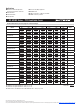
Product Dimensions (see previous page for dimensions)
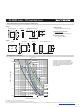
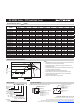
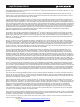
Typical Time to Trip at 23 °C
0.001
0.01
0.1
1
10
100
0.1 110 100
MF-MSMF020
MF-MSMF030
MF-MSMF200
MF-MSMF010
MF-MSMF050
MF-MSMF075
MF-MSMF075/24
MF-MSMF110
MF-MSMF110/16
MF-MSMF250/16X
MF-MSMF150
MF-MSMF160
MF-MSMF260
0.01
0.001
0.1
110 100
0.1
1
10
100
Fault Current (Amps)
Time to Trip (Seconds)
MF-MSMF200L
MF-MSMF110L
MF-MSMF150L
MF-MSMF160L
0.01
0.001
0.1
110 100
0.1
1
10
100
Fault Current (Amps)
OLD
Time to Trip (Seconds)
Fault Current (Amps)
Time to Trip (Seconds)
MF-MSMF075/24
MF-MSMF250/16X
MF-MSMF150/24X
MF-MSMF110/16
0.01
0.001
0.1
110 100
0.1
1
10
100
Fault Current (Amps)
Time to Trip (Seconds)
MF-MSMF075/24
MF-MSMF250/16X
MF-MSMF150/24X
MF-MSMF110/24X
MF-MSMF110/16
MF-MSMF125
MF-MSMF050/40X
MF-MSMF050/30X
MF-MSMF110/24X
MF-MSMF150/24X
MF-MSMF150/12
MF-MSMF014 & MF-MSMF020/60
The Time to Trip curves represent typical
performance of a device in a simulated
application environment. Actual performance
in specic customer applications may differ
from these values due to the inuence of
other variables.
Specifications are subject to change without notice.
Users should verify actual device performance in their specific applications.
The products described herein and this document are subject to specific legal disclaimers as set forth on the last page of this document, and at www.bourns.com/docs/legal/disclaimer.pdf.