
Datasheet

Specifications are subject to change without notice.
Users should verify actual device performance in their specific applications.
The products described herein and this document are subject to specific legal disclaimers
as set forth on the last page of this document, and at www.bourns.com/docs/legal/disclaimer.pdf.
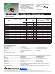
MF-MSMF Series - PTC Resettable Fuses
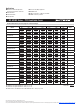
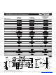
Thermal Derating Chart - I
hold
(Amps)
Model
Ambient Operating Temperature
-40 ˚C -20 ˚C 0 ˚C 23 ˚C 40 ˚C 50 ˚C 60 ˚C 70 ˚C 85 ˚C
MF-MSMF010 0.16 0.14 0.12 0.10 0.08 0.07 0.06 0.05 0.03
MF-MSMF014 0.23 0.19 0.17 0.14 0.12 0.10 0.09 0.08 0.06
MF-MSMF020 0.29 0.26 0.23 0.20 0.17 0.15 0.14 0.12 0.10
MF-MSMF020/60 0.29 0.26 0.23 0.20 0.17 0.15 0.14 0.12 0.10
MF-MSMF030 0.44 0.39 0.35 0.30 0.26 0.23 0.21 0.18 0.15
MF-MSMF050 0.77 0.68 0.59 0.50 0.44 0.40 0.37 0.33 0.29
MF-MSMF050/30X 0.77 0.68 0.59 0.50 0.44 0.40 0.37 0.33 0.25
MF-MSMF050/40X 0.77 0.68 0.59 0.50 0.44 0.40 0.37 0.33 0.25
MF-MSMF075 1.15 1.01 0.88 0.75 0.65 0.60 0.55 0.49 0.43
MF-MSMF075/24 1.15 1.01 0.88 0.75 0.65 0.60 0.55 0.49 0.43
MF-MSMF110 1.59 1.43 1.26 1.10 0.95 0.87 0.80 0.71 0.60
MF-MSMF110/16 1.59 1.43 1.26 1.10 0.95 0.87 0.80 0.71 0.60
MF-MSMF110/24X 2.00 1.70
1.40 1.10 0.95 0.88 0.80 0.73 0.61
MF-MSMF125 1.80 1.63 1.43 1.25 1.08 0.99 0.91 0.81 0.68
MF-MSMF150 2.17 1.95 1.72 1.50 1.30 1.18 1.09 0.97 0.82
MF-MSMF150/12 2.17 1.95 1.72 1.50 1.30 1.18 1.09 0.97 0.82
MF-MSMF150/24X 2.10 1.90 1.70 1.50 1.25 1.13 1.00 0.88 0.69
MF-MSMF160 2.30 2.20 1.90 1.60 1.45 1.30 1.15 1.03 0.91
MF-MSMF200 3.08 2.71 2.35 2.00 1.80 1.60 1.50 1.40 1.25
MF-MSMF250/16X 3.90 3.42 2.96 2.50 2.24 1.98 1.85 1.29 0.94
MF-MSMF260 4.00 3.52 3.06 2.60 2.34 2.08 1.95 1.39 1.04
Solder Reow Recommendations
How to Order
MF - MSMF 075/24 - 2
Multifuse
®
Product
Designator
Series
MSMF = 4532 mm (1812 mils)
Surface Mount Component
Hold Current, Ihold
010-260 (0.10 Amps - 2.60 Amps)
Higher Voltage Option
Blank = Standard Voltage
/12, /16, /24,
/30, /40, /60 = Specic Voltage Rated
X = Multifuse
®
freeXpansion
Design
™
MF-MSMF Series
Packaging
Packaged per EIA 481-1
-2 = Tape and Reel
Typical Part Marking
Represents total content. Layout may vary.
PART IDENTIFICATION EXAMPLES:
MF-MSMF020 = 02
MF-MSMF050 = 50
MF-MSMF075 & 075/24 = 75
MF-MSMF110 & 110/16 = 11
MF-MSMF150 & 150/12 = 15
MF-MSMF200 = 20
115Y
YEAR CODE:
5 = 2005
BI-WEEKLY DATE CODE:
WEEKS 49-50 = Y
MF-MSMF020/60 = 2
MF-MSMF050/30X & /40X = 4
MF-MSMF110/24X = 6
MF-MSMF150/24X = 8
MF-MSMF250/16X = C
BI-WEEKLY DATE CODE:
WEEKS 5-6 = C
8
C
MF-MSMF SERIES, REV. AO, 05/18
PART IDENTIFICATION EXAMPLES:
MF-MSMF020 = 02
MF-MSMF050 = 50
MF-MSMF075 & 075/24 = 75
MF-MSMF110 & 110/16 = 11
MF-MSMF150 & 150/12 = 15
MF-MSMF200 = 20
115Y
YEAR CODE:
5 = 2005
BI-WEEKLY DATE CODE:
WEEKS 49-50 = Y
PART IDENTIFICATION EXAMPLES:
MF-MSMF020/60 = 2
MF-MSMF050/30X & /40X = 4
MF-MSMF110/24X = 6
MF-MSMF150/24X = 8
MF-MSMF250/16X = C
BI-WEEKLY DATE CODE:
WEEKS 5-6 = C
8
C
Notes:
• MF-MSMF models cannot be wave soldered or hand soldered. Please
contact Bourns for soldering recommendations.
• All temperatures refer to topside of the package, measured on the
package body surface.
• If reow temperatures exceed the recommended prole, devices may
not meet the published specications.
• Compatible with Pb and Pb-free solder reow proles.
• Excess solder may cause a short circuit, especially during hand
soldering. Please refer to the Multifuse
®
Polymer PTC Soldering
Recommendation guidelines.
• Designed for single solder reow operations.
Temperature of Lead/Pad Junction
Process
Materials Temperature
Time
Description Interval
1. Apply solder paste to • Sn 96.5 / Ag 3.0 / Cu 0.5 Room temperature
test board (8 - 10 mil thick) Alloy water soluble or no
clean solder paste
(see note 1)
• single sided epoxy glass
(G10) (UL approved)
• PC board approx. 4x4x.06 in.
2. Place test units onto board 6 units/board
3. Ramp up Convection oven (see note 2) 2.5 °C ± 0.5 °/sec.
4. Preheat (T
S
.ces03±09C°091otC°051)
5. Time above liquidus (T
L
.ces09-06C°022)
6. Peak temperature (T
P
°5-/°0+C°052)
10-20 sec. within
5 °C of peak
.ces/C°5.0±C°3erutarepmetmooRnwodpmaR.7
(see note 2)
8. Cleaning water clean profile High pressure deionized 72 °F to 160 °F As required
water 65 PSI max. (22 °C to 71 °C)
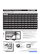
Inspect solder joint to determine if solder joint is
acceptable (i.e. exhibits wetting of joint’s surface).
Use the following criteria (ref. acceptability of printed
board assemblies, IPC-A-610):
A) Acceptable (see Figure 1)
(1) The solder connection wetting angle (solder to
component and solder to PCB termination)
does not exceed 90 °.
(2) Solder balls that do not violate minimum
electrical clearances and are attached
(soldered) to a metal surface.
B) Unacceptable (see Figure 2)
(1) Solder connection wetting angle exceeding
90 °.
(2) Incomplete reflow of solder paste.
(3) Dewetting.
If unacceptable, determine cause and correct prior to
next run.
NOTES:
1. Water soluble solder paste only above 100K.
2. Refer to ref. temperature profile. Temperature at
lead/pad junction with “K” type thermocouple.
3. Units that are board mounted for environmental
testing must see a peak temperature in the reflow
zone, as specified. This is to ensure that all test
units will see “worst case conditions”.
4. Ramp down rate to be measured from 245 °C to
150 °C.
5. Process Description 8 does not apply to open
frame trimmers.
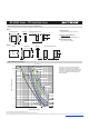
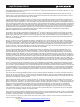
(Derived using 6-zone Convection Oven)
T
P
T
P
t
p
t
s
TTO
RAMP-UP
L
T
L
t
L
T MAX.
S
T MIN.
25
PREHEAT
S
Temperature
Time
CRITICAL ZONE
RAMP-DOWN
8 MINS.
t 25 *C TO PEAK