
Datasheet

Asia-Paci fic: Tel +886-2 256 241 17
asiacus@bourns.com
Americas: Tel +1-951 781-5500
americus@bourns.com
EMEA: Tel +36 88 885 877
eurocus@bourns.com
PRODUCT CHANGE NOTIFICATION
Users should verify that the described changes will not impact the performance of the product in their specific applications.
MAGNETICS
Current Carrier Pocket – Closed Bottom Revised Carrier Pocket – 1 mm Diameter Bottom Hole
Implementation dates are as follows:
First date code using the above changes: 2007
If you have any questions or need additional information, please feel free to contact Customer Service/Inside Sales.
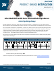
Select Model SRF and SM Series Common Mode Chip Inductors
Carrier Tape Design Change
Riverside, California – February 24, 2020 – Effective immediately, Bourns is changing the carrier tape design of select
SRF and SM Series Common Mode Chip Inductors to include a 1 mm diameter hole at the bottom of the carrier pocket.
The carrier pocket currently has a closed bottom. In some cases, when the carrier tape is peeled away during assembly,
the process itself can generate a level of electrostatic discharge high enough to attract small components remaining
in the pocket which can interfere with the component picking process. Research shows that the open hole at the
bottom of the carrier pocket can dramatically reduce the static voltage to a level that will not interfere with the
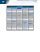
assembly process. A list of affected part numbers is included on the following page.
The change in carrier tape design has no effect on the component. The form, fit, function, reliability and quality of the
inductor remain unchanged.
IC1921A