
TreadClimber Assembly Manual


Assembly Manual
9
Assembly
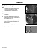
Step 4: Attach the Drive Belt
Parts:
• TreadClimber
®
Base and Treadle assembly from Step 3
• (1) Drive Belt
Tools:
• 3/16” Hex Key (included)
4-1 Position the drive belt over the roller pulley and the motor
pulley (See Figure 4-1).
4-2 Make sure that the belt is installed correctly into the grooves
of the pulleys (See Figure 4-2).
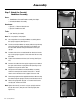
4-3 Remove the motor shipping bolt from the motor pan with
the 3/16” hex key (See Figure 4-3).
Note: Removing the shipping bolt will make the drive belt tight with
spring-loaded tension. Be sure to keep the bolt in a safe place
in case the machine must be disassembled for shipping or part
replacement.
4-4 Put the unit in the upright position.
Figure 4-1
Figure 4-2
Figure 4-3
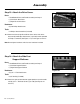
Figure 3-1
Lever in locked position
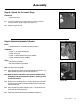
Step 3: Lock the Treadles
Parts:
• TreadClimber
®
Base and Treadle assembly from Step 2
3-1 Line up the treadles parallel to each other and cut the zip
tie connecting them.
3-2 Move the locking lever down and to the left and then up into
the locked position until it clicks (See Figure 3-1).
3-3 From the front of the machine, press down on each treadle
individually until they lock into the down position.
The treadles might unlock during workout if they are not fully engaged.