COMMERCIAL ELECTRIC WATER HEATER La estas of instrucciones se puede obtener al a A version Spanishespanola languagede version these instructions is available byescribirle contacting lathe fábrica cuyo listed nombre la placa de especificaciones. company on aparece the ratinginplate. ALa Spanish of instrucciones these instructions is available byalcontacting versiónlanguage espãnolaversion de estas se puede obtener escribirle the on aparece the ratingenplate.
TABLE OF CONTENTS General Information .......................................................... 3 Installation ......................................................................... 4 Locating The Water Heater.................................................... Water Connections ................................................................ Electrical Connections .......................................................... Amperage Chart ..................................................................
GENERAL INFORMATION The design of this electric water has been listed with Underwriters’ Laboratories, Inc. (UL) as complying with UL standard UL1453. This water heater must be installed in accordance with local codes. In the absence of local codes, install this water heater in accordance with the N.E.C. Reference Book (latest edition).
General Information continued- A sacrificial anode(s) is used to extend tank life. Removal of any anode, for any reason, will nullify the warranty. In areas where water is unusually active, an odor may occur at the hot water faucet due to a reaction between the sacrificial anode and impurities in the water. If this should happen, an alternative anode(s) may be purchased from the supplier that installed this water heater. This will minimize the odor while protecting the tank.
Locating The Water Heater continued- It is recommended that the water heater be located near the center of greatest hot water usage to prevent heat loss through the pipes. DO NOT locate the water heater where water lines could be subjected to freezing temperatures. Locate the water heater so that access panels and drain valves are accessible. Water heater corrosion and component failure can be caused by the heating and breakdown of airborne chemical vapors.
Water Connections NOTE: BEFORE PROCEEDING WITH THE INSTALLATION, CLOSE THE MAIN WATER SUPPLY VALVE. After shutting the main water supply valve, open a faucet to relieve the water line pressure to prevent any water from leaking out of the pipes while making the water connections to the water heater. After the pressure has been relieved, close the faucet. The cold water inlet line connects to the inlet nipple at the base of the water heater.
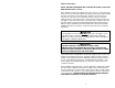
Water Connections continued- WARNING For protection against excessive temperatures and pressure, install temperature and pressure protective equipment required by local codes, but not less than a combination temperature and pressure relief valve certified by a nationally recognized testing laboratory that maintains periodic inspection of production of listed equipment or materials, as meeting the Requirements for Relief Valves and Automatic Gas Shutoff Devices for Hot Water Supply Systems, ANSI Z21.
Water Connections continued- WARNING Hydrogen gas can be produced in a hot water system served by this water heater that has not been used for a long period of time (generally two weeks or more). Hydrogen gas is extremely flammable. To reduce the risk of injury under these conditions, it is recommended that the hot water faucet be opened for several minutes at the kitchen sink before using any electrical appliance connected to the hot water system.
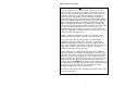
Water Connections continuedWater temperature over 125°F can cause severe burns instantly or death from scalds. Children, disabled and elderly are at highest risk of being scalded. Review this instruction manual before setting temperature at water heater. Feel water before bathing or showering. Temperature limiting valves are available.
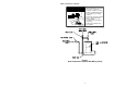
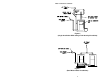
Water Connections continued- Figure 2 (Single Installation With Storage Tank Gravity Circulation) Figure 3 (Dual Water Heater Installation) 10
Electrical Connections Before any electrical connections are made, be sure that the water heater is full of water and that the manual shut-off valve in the cold water supply line is open. If the heating elements are not completely immersed in water at all times, they will be damaged (burned-out) if energized for even a short period of time. The warranty does not cover burned-out heating elements. Check the rating plate and wiring diagram before proceeding.
Electrical Connections continued- Amperage Chart kW 208V 240V 277V 380V 415V 480V Input 1Ø 3Ø 1Ø 3Ø 1Ø 3Ø 3Ø 1Ø 3Ø 6 29 17 25 14 22 9 8 12 7 9 43 25 38 22 32 14 13 19 11 12 58 33 50 29 43 19 17 25 14 13.
GENERAL OPERATION Before closing the switch to allow electric current to flow to the water heater, make certain that the water heater is full of water and that the cold water inlet valve is open. Complete failure of the heating elements will result if they are not totally immersed in water at all times. When the switch is closed, the operation of this electric water heater is automatic. The thermostat(s) are preset to provide a water temperature of approximately 140°F (60°C) or below.
Thermostat Adjustment There are two types of thermostats this electric water heater may come equipped with from the factory. One type, surface mounted thermostats, directly contacts the water heater tank surface (see Figure 4). The second type, immersed type are immersed within the water heater tank and uses contactor type relays. Before any work is done on the water heater, disconnect all power to the water heater by opening the switch at the main electrical circuit breaker or fuse box.
Thermostat Adjustment continued- Figure 4 Figure 5 15
MAINTENANCE IMPORTANT The water heater should be inspected at a minimum of annually by a qualified service technician for damaged components. DO NOT operate this water heater if any part is found damaged. Shut off the electric power whenever the water supply to the water heater is off. Shut off the electric power and water supply, drain the heater completely to prevent freezing whenever the building is left unoccupied during the cold weather months.
Maintenance continued- 3. At least once a year, check the combination temperature and pressure relief valve to insure that the valve has not become encrusted with lime. Lift the lever at the top of the temperature-pressure relief valve several times until the valve seats properly without leaking and operates freely. WARNING When lifting lever of temperature-pressure relief valve, hot water will be released under pressure.
Maintenance continued- Contact your local plumbing supplier or plumbing professional for replacement parts or contact the company at the address displayed on the rating plate of the water heater. For faster and better service, please provide the part name, model, and serial number(s) of the water heater(s) when ordering parts. READ THE WARRANTY FOR A FULL EXPLANATION OF THE LENGTH OF TIME THAT PARTS AND THE WATER HEATER ARE WARRANTED. Manufactured under one or more of the following U.S. Patents: RE.
NOTES 19
COMMERCIAL ELECTRIC ENERGY SAVER WATER HEATER MII SERIES IMMERSION AND SURFACE MOUNTED THERMOSTAT MODELS SERVICE MANUAL Troubleshooting Guide and Instructions for Service (To be performed ONLY by qualified service providers) Models Covered by This Manual: MII50(A)-*-**-(SF,CF,SCF)-*** MII80(A)-*-**-(SF,CF,SCF)-*** MII120(A)-*-**-(SF,CF,SCF)-*** *Denotes kW Rating **Denotes Warranty Years ***Denotes Wiring Code Manual 238-47174-00B Save this manual for future reference
MII Series Commercial Electric Water Heaters Table of Contents Page Service Procedure Introduction ………………………………………………………………………. 2 --- Tools……………………………………………………………………………… 2 --- General Information ……………………………………………………………… 3 --- Sequence of Operation …………………………………………………………… 10 --- Troubleshooting …………………………………………………………………. 13 --- Heating Element Testing …………….................................................................... 15 MCE-I Line Voltage Testing………………...
GENERAL INFORMATION Bradford White MII Series Commercial Electric water heaters can be manufactured with a choice between two different types of thermostat control options as follows: Surface Mounted Thermostats. Immersion Thermostat (contactor models). The model number is coded to identify the specific thermostat control system used for a particular unit.
GENERAL INFORMATION Contactor Models General Controls Layout Ground Lug Terminal Block Upper Control Box Fuse Block(s) Contactor(s) High Limit (ECO) Direct Immersion Bulb Thermostat Direct Immersion Bulb High Limit (ECO) Control Immersion Thermostat Control Lower Control Box Heating Elements Surface Mounted Thermostat Models General Controls Layout Ground Lug Terminal Block Upper Control Box Fuse Block(s) Surface Mounted Thermostats With ECO Lower Control Box Heating Elements Page 4 4
GENERAL INFORMATION 600V Surface Thermostat (w/Contactors) Models General Controls Layout Terminal Block Ground Lug Upper Control Box Contactor(s) High Limit (ECO) Control Surface Thermostats Lower Control Box Heating Elements Page 5 5
GENERAL INFORMATION Surface Mounted Thermostats Surface mounted thermostats are mounted into a bracket above each heating element. The bracket holds the thermostat against the side of the tank responding to tank surface temperatures to sense a call for heat, set point temperature and high limit (ECO) activation. As each element has a dedicated thermostat (for all models excluding 600V), it is possible to sequence the elements by varying the settings on the thermostats.
GENERAL INFORMATION Surface Mounted Thermostats (w/Contactors) for 600V Models 600V models use contactors to deliver line voltage to the heating elements. However, rather than the immersion type high limit and thermostat devices, surface mounted thermostats are used to operate the control circuit of the water heater.
GENERAL INFORMATION Contactor Contactor operation is achieved by energizing an operating coil in response to a call for heat from the immersion thermostat. Upon a call for heat, one or more contactors will energize all heating elements simultaneously. The operating coils are voltage specific, When contactor replacement is required be sure to order the proper operating coil base on the voltage rating found on the rating plate located on the front of the water heater.
GENERAL INFORMATION Commonly Used Formulas (balanced 3 phase) Watts Amps = Volts x 1.
SEQUENCE OF OPERATION MII Series Commercial Electric Water Heaters can use either immersion thermostat (contactor models) or surface mounted thermostats. Sequence of operation for each configuration is explained below. It would be impractical to show all wire diagrams applicable to both configurations. A “typical wiring diagram” is illustrated to aid in understanding the principles of the operating sequence.
SEQUENCE OF OPERATION Sequence of Operation: Surface Mounted Thermostats. Line Voltage 1 Fuse Block 1 OR Terminal Block Line voltage is applied across terminals of fuse block or a terminal block. Line voltage continues down and connects to surface mounted thermostats at terminals L1 & L3. 2 2 ECO (high limit) in thermostat is closed, so there is line voltage present at terminal L4 of thermostats and to one side of each element.
SEQUENCE OF OPERATION Sequence of Operation: 600V Surface Mounted Thermostats (w/Contactors). 6 Element Configuration Shown (9 Elements Possible) The system has two distinct circuits. 1. Power circuit - Line Voltage (600V) 2. Control Circuit - 120V 1 Line Voltage Fuse Block Transformer 60VA Line voltage is applied across terminals of fuse block or a terminal block. Line voltage continues down and connects to terminals L1, L2 & L3 of one or more contactors.
TROUBLESHOOTING Most common cause for improper electric water heater operation can be linked to heating element failure. When troubleshooting an electric water heater with the incidence of “No Hot Water” or “Insufficient Amount of Hot Water” It is always a good idea to check the heating elements first following the procedure on page 15. Common Heating Element Failures Are: 1. Dry Firing. Elements may be partially submerged in water or most likely, completely exposed with no water in the tank at all.
TROUBLESHOOTING Quick Step Plan to Hot Water 1. STOP, DANGER! Turn power “OFF” to water heater. 2. Check all wire connections to insure they are snug and corrosion free. WARNING High voltage exposure. Use caution when making voltage checks to avoid hazard to life or property. 3. Reset high limit (ECO) (page 18-20). 4. Check for inoperative heating element (page 15). 5. Check line voltage (pg 16), and internal fuses (page 17). 6. Refer to table below if items 1 through 5 above do not correct problem.
SERVICE PROCEDURE MCE-I Heating Element Testing Test for Open or Burned Out Element. 1. STOP, DANGER! Turn power “OFF” to water heater. 2. Remove access cover from lower control box. Remove insulation from inside of control box. 3. Disconnect wires from heating element. DANGER High voltage exposure. To avoid hazard to Life or property, be sure power is turned OFF to water heater while performing this procedure. 4. Set multi-meter to “ohms” setting. 5.
SERVICE PROCEDURE MCE-II Line Voltage Testing DANGER High voltage exposure. To avoid hazard to life or property use extreme caution when making voltage checks . Line Voltage Testing Line voltage (single phase or three phase) will connect to a terminal block or directly to a fuse block located inside control panel. Determine heaters voltage and phase by referring to the rating plate located on the front of the heater.
SERVICE PROCEDURE MCE-III Fuse Testing Fuse Testing DANGER High voltage exposure. To avoid hazard to Life or property, be sure power is turned OFF to water heater while performing this procedure. 1. Turn “OFF” power to water heater. 2. Open upper control box to allow access to fuse block. 3. Locate fuse block and remove fuses. 4. Set multi-meter to the “Ohms” setting. 5. Check continuity across fuse (see illustration 5). A) Continuity IS present, fuse is okay.
SERVICE PROCEDURE MCE-IV High Limit (ECO) Testing DANGER High voltage exposure. To avoid hazard to life or property use extreme caution when making voltage checks . High Limit Control (ECO) Testing for Surface Thermostat models (not including 600V) 1. This procedure assumes line voltage and fuses are in working order. 2. This procedure illustrates testing of just one surface thermostat. Repeat this procedure for all surface thermostats on the unit. ECO reset button 3. Turn power “OFF” to water heater.
SERVICE PROCEDURE MCE-V High Limit (ECO) Testing DANGER High voltage exposure. To avoid hazard to life or property use extreme caution when making voltage checks . High Limit Control (ECO) Testing for 600V Surface Thermostat Models 1. This procedure assumes line voltage, transformer, fuses, and thermostat are in working order. ECO reset button 2. Turn power “OFF” to water heater. 3. Remove lower control box cover and remove insulation from inside of control box. 4.
SERVICE PROCEDURE MCE-VI High Limit (ECO) Testing High Limit Control (ECO) Testing for Contactor Models Switch Contacts: Normally closed. Open on rise @ 196°F ±4°F Manual Reset. Observe heating cycle. Does switch open? N Is water temp over 196°F Y N Y 1. Determine if Hi-Limit has actuated. This can be done by simply depressing the reset buttons. If you hear and/or feel a small click, the switch has actuated. 2.
SERVICE PROCEDURE MCE-VII Thermostat Testing Surface Mounted Thermostat. Operation Testing (not including 600V models) DANGER High voltage exposure. To avoid hazard to life or property, use extreme caution when making voltage checks . Water In Tank Is Cold With Power ON. 1. This procedure assumes line voltage, ECO and elements are in working order. 2. TURN OFF POWER TO WATER HEATER. 3. Remove access cover from lower control box. Remove insulation from inside of control box.
SERVICE PROCEDURE MCE-VIII Thermostat Testing 600V Surface Mounted Thermostat Models. Operation Testing DANGER High voltage exposure. To avoid hazard to life or property, use extreme caution when making voltage checks . Water In Tank Is Cold With Power ON. 1. This procedure assumes line voltage, ECO, transformer thermostat, and elements are in working order. 2. TURN OFF POWER TO WATER HEATER. 3. Remove access cover from lower control box. Remove insulation from inside of control box. 4.
SERVICE PROCEDURE MCE-IX Thermostat Testing Immersion Thermostat Operation Testing DANGER High voltage exposure. To avoid hazard to life or property use extreme caution when making voltage checks .
SERVICE PROCEDURE MCE-X Contactor Testing DANGER High voltage exposure. To avoid hazard to life or property, use extreme caution when making voltage checks . Contactor Operation Testing Noisy Contactor Noisy or chattering contactor operation in most cases is due to voltage variations being supplied to the water heater. Extended periods of voltage variations will cause damage to the operating coil of the contactor causing noisy operation.
SERVICE PROCEDURE MCE-X Contactor Testing Contactor Operation Testing (continued) This procedure assumes control circuit is operating correctly. Providing the water temperature in tank is within the operating range of the thermostat, checking contactor operation can be as simple as rotating the thermostat dial and listening to the contactor(s) to see if they respond to a call for heat. DANGER High voltage exposure. To avoid hazard to life or property, use extreme caution when making voltage checks . 1.
SERVICE PROCEDURE MCE-XI Thermostat Removal and Replacement Surface Mounted Thermostat Removal 1. STOP, DANGER! Turn power “OFF” to water heater. 2. Remove access cover from lower control box. Remove insulation from inside of control box. Remove plastic cover from thermostat. DANGER High voltage exposure. To avoid hazard to Life or property, be sure power is turned OFF to water heater while performing this procedure. 3. Disconnect wires from thermostat terminals.
SERVICE PROCEDURE MCE-XII Thermostat Removal and Replacement DANGER High voltage exposure. To avoid hazard to Life or property, be sure power is turned OFF to water heater while performing this procedure. Immersion Thermostat Removal & Replacement 1. STOP, DANGER! Turn power “OFF” to water heater. 2. Turn off cold water supply to heater. Connect hose to drain spigot of water heater and route to an open drain. Open a nearby hot water faucet to vent heater for draining.
SERVICE PROCEDURE MCE-XIII Contactor Model High Limit (ECO) Control Removal and Replacement Contactor Model High Limit (ECO) Control Removal and Replacement 1. STOP, DANGER! Turn power “OFF” to water heater. 2. Turn off cold water supply to heater. Connect hose to drain spigot of water heater and route to an open drain. Open a nearby hot water faucet to vent heater for draining. Open drain spigot of water heater and allow heater to drain to a point below the Immersion bulb location (see illustration 18).
SERVICE PROCEDURE MCE-XIV 600V Model High Limit (ECO) Control Removal and Replacement DANGER High voltage exposure. To avoid hazard to Life or property, be sure power is turned OFF to water heater while performing this procedure. 600V Surface Thermostat Model High Limit (ECO) Control Removal and Replacement 1. STOP, DANGER! Turn power “OFF” to water heater. 2. Remove lower control box cover and insulation. 3. Locate high limit switch mounted to the tank above the element spuds (see illustration 20). 4.
SERVICE PROCEDURE MCE-XV Heating Element Removal and Replacement Heating Element Removal 1. STOP, DANGER! Turn power “OFF” to water heater. 2. Turn off cold water supply to heater. Connect hose to drain spigot of water heater and route to an open drain. Open a nearby hot water faucet to vent heater for draining. Open drain spigot of water heater and allow heater to drain to a point below the Element(s). 3. Close drain spigot and remove hose. 4. Remove access cover from lower control box.
SERVICE PROCEDURE MCE-XVI Anode Inspection and Replacement Anode Inspection and Replacement DANGER High voltage exposure. To avoid hazard to Life or property, be sure power is turned OFF to water heater while performing this procedure. WARNING Heater components and stored water may be HOT when performing the following steps in this procedure. Take necessary precaution to prevent personal injury. 1. Turn power “OFF” to water heater. 2. Turn off cold water supply to heater.
Generic Parts List Page 32 32
Generic Parts List Item 1 2 3 3A 4 5 5A 6 7 8 9 10 10A 11 11A 12 12A 13 14 15 16 17 18 19 20 21 22 23 24 25 Description Anode. Hot Water Outlet Nipple. T&P Nipple. T&P Coupling. T&P Relief Valve. High Limit Switch. Surface High Limit Switch. Hex Nut Lock Washer Screw High Limit Spacer. Cleanout O-Ring. Cleanout Gasket (ASME). Cleanout Cover. Cleanout Cover (ASME). Cleanout Cover Screw. Cleanout Cover Screw (ASME) Cleanout Access Cover. Brass Drain Valve. Escutcheon. Drain Extender. Thermostat Dial Screw.
NOTES Page 34 34
NOTES Page 34 35
Email parts@bradfordwhite.com techserv@bradfordwhite.com www.bradfordwhite.