
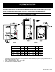
Specifications

2
SECTION V: VENTING
The water heater models described above in this supplement are of the induced draft type which rely on an
induced draft blower to pull the combustion products through the flue tubes of the water heater. An integral
gravity damper on the induced draft blower outlet is forced open by the air pressure from the blower and closes
at the end of each burner cycle. NO ADDITIONAL VENT DAMPERS ARE TO BE ATTACHED TO THE OUTLET OF
THESE APPLIANCES.
These water heaters have been approved for vertical venting through a lined masonry chimney or double wall
vent pipe. DO NOT VENT THESE WATER HEATERS HORIZONTALLY WITH THE VENT TERMINATING THROUGH
THE WALL TO THE OUTSIDE. ALL VENTING MUST TERMINATE THROUGH THE ROOF WITH A VERTICAL
DISCHARGE.
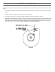
The vent connector attached to the vent collar on the blower must be 8" (20 cm) in diameter. The venting size was
designed to produce a negative pressure inside the venting system when properly installed. Horizontal piping must be
sloped upward at least 1/4" inch per linear foot (2.1 cm/m) of length. All vent piping must be well supported to avoid
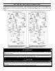
sagging or adding excessive weight onto the blower assembly. This water heater may be commonly vented with another
gas appliance, providing the commonly shared vent is the proper size to handle exhaust gases from both appliances. For
proper venting, limit the number of elbows in the venting system. All connections in the venting system must be securely
fastened with sheet metal screws or other approved methods. Consult local codes and ordinances. See Figures 2 & 3 on
the below for common venting connections.
Figure 2 Figure 3
This water heater must not have another gas appliance vented into the vent connector. Consult the venting
tables in the latest edition of the National Fuel Gas Code ANSI Z223.1 or in Canada CAN1-B149.1 or B149.2 and/or
local code officials for proper application for your area.
Failure to install a proper venting system can result in fire, injury, or death.
WARNING