PDV(S,T) MODEL SERIES AND INDUCED DRAFT (D80T725, D65T625) MODEL SERIES WATER HEATERS WITH HONEYWELL INTEGRATED CONTROL SYSTEM SERVICE MANUAL Troubleshooting Guide and Instructions for Service (To be performed ONLY by qualified service providers) PDV80S150 PDV802200 PDV80S250 PDV100S150 PDV100S200 PDV100S250 PDV80T300 PDV100T360 D80T725 D65T625 (PDV80S Shown) Manual 48061A Save this manual for future reference
Table of Contents Page PDV Service Procedure Introduction 4 --- Tool required for service 4 --- Sequence of Operation 6 --- Troubleshooting 7 --- Thermostat Circuit Testing 24 PDV24-I Pressure Switch Testing 27 PDV24-II Pilot Operation Testing 30 PDV24-III Main Burner Operation Testing 33 PDV24-IV Main Burner & Pilot Removal & Inspection 35 PDV24-V Control Board Replacement 40 PDV24-VI Flue Baffle Removal & Inspection 41 PDV24-VII Anode Removal & Inspection 42 PDV24-VII
FEATURES OF PDV-S MODEL SERIES Power vented direct vent design, uses a blower to vent the flue products to the outside and pull combustion air in from outside the building Independent Venting - Exhausts flue products and supplies combustion air through two separate 3" or 4" PVC, CPVC or ABS pipes. Maximum venting distance of 40 ft. with one 90 degree elbow for each pipe in 3". The 250,000 Btu/hr. model vents with 4" PVC, CPVC, or ABS only.
Introduction It is intended for this manual to be used by qualified service personal for the primary purpose of troubleshooting analysis and repair of the Bradford White PDV & Induced Draft Series Water Heaters. Understanding the sequence of operation section of this manual will contribute greatly to troubleshooting this product.
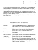
Specifications Power Supply Dedicated 120 VAC, 60 Hz., 15 A Current Draw Less than 5 Amps Gas Supply Connection Approved Gas Type Gas Pressure (Nat. & L.P.) PDV-S & PDV-T MODELS: 3/4" NPT Minimum connection to gas valve. INDUCED DRAFT MODELS: 1" NPT Minimum conncection to gas valve. Schedule 40 black iron pipe recommended for all models. Natural or Propane. Gas supply must match the gas type listed on the water heater rating label. Manifold Pressure: 4.5" w.c. natural gas, 10.0" w.c. L.P.
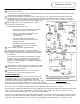
Sequence of Operation 1 2 3 Thermostat calls for heat: . The relay closes on the control board, sending line voltage (115-120 volts) from “inducer” terminals #5 and 3 on the control board to the induced draft blower. The blower starts and when sufficient vacuum is achieved, the pressure switch closes and completes the 24 volt circuit between terminals 1 and 3 on the Control Plug to the the board, allowing the ignition sequence to proceed.
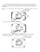
TROUBLESHOOTING CAUTION Use Caution Not to Damage Connectors when making Voltage Measurements or Jumping Terminals Water Heater Fault: Water heater does not operate Display Error Code: Water heater display does not operate - blank display Check main power supply to water heater - fuse, circuit breaker, plug receptacle, line cord or wiring to water heater. Check to make sure switch on top of control panel is in the ON position Checking line voltage to board. Pins to black and white wires.
TROUBLESHOOTING CAUTION Use Caution Not to Damage Connectors when making Voltage Measurements or Jumping Terminals From previous page Error code #29 on display. Measure voltage at the pin terminals on the control board between the black and white wires to the blower (terminals 5 and 3 on the “inducer” output on the board, see image above). Make sure the control display shows “heating” in the status mode. Increase the setpoint, if it does not show “heating”.
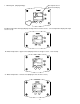
ACCESSING SERVICE MODE ON THE WATER HEATER DISPLAY (FOR SERVICE PERSONNEL ONLY) The display has a “service mode” for changing the maximum setpoint and accessing information in aiding servicing of the water heater. This procedure is for service and installation personnel only. To enter the Service Mode, follow the steps illustrated below: Step 1: Press “Select” and “Temperature Up” buttons together and hold for 3 seconds until “Max Setpoint” is shown in the display.
1. Max Setpoint (Display/Change) Max Setpoint value in Water Heater Display °F Max Setpoint idle Status Operational E SELECT SET 2a. Water Temperature Average (Displays average if there are two sensors - sensor temperature displayed if single sensor is used). °F Water Temp idle Status Operational SELECT SET 2b. Water Temperature - Upper Sensor (Displays if there is an upper sensor - some models) °F idle Status Operational Upper Sensor SELECT SET 2c.
3. Flame Current of Pilot Flame Sensor (Displays only in the Heating Cycle) µA Heating Status Flame Current Operational SELECT SET 4. Setpoint (Display/Change) °F setpoint idle Status Operational SELECT 5. SET °F/°C (Display/Change) °F °F/C° setpoint idle Status Operational SELECT 6.
7. Software Version (Display only) Soft idle Status Operational SELECT 8. SET Error Code History (Displays if there are present error codes or up to 10 previous error codes). Water Heater Display will show a “--“ if there are no error codes. idle Status Operational SELECT SET To change the Maximum Setpoint Limit (Max Setpoint) for the temperature setpoint: Step 1: In service mode press the “Select” button until “Max Setpoint” is displayed.
Step 2: Press “Set” button to enter setting mode. “Max Setpoint” will flash to indicate setting mode. Max Setpoint °F idle Status Operational SELECT SET Step 3: Press the “UP” or “DOWN” buttons to change the maximum setpoint value. This will limit the maximum setpoint the user can select. Note: The maximum setpoint is approximately 180°F.
Step 5: 30 Seconds after the last button press, the Water Heater Display will go back to “User Mode”. It will read “Max Setpoint” without showing a temperature value if the temperature setpoint is at the maximum setting. The Water Heater Display can be set back to the “User Mode” immediately by pressing both the “Temperature Up” and “Select” buttons together for 3 seconds.
Step 3: For water heaters using two temperature sensors, pressing the “Select” button again displays the Lower Sensor temperature reading. “Lower Sensor” will be displayed in the lower left side of the status window of the water heater display. °F idle Status Operational Lower Sensor SELECT SET To Display Flame Sense Current of the Pilot Flame Sensor: The pilot flame sense current is available only when the burners are in operation.
Step 2: Press the “Set” button to enter the setting mode. “Setpoint” will flash in the water heater display. °F setpoint idle Status Operational SELECT SET Step 3: To raise the temperature setpoint, press the “Temperature Up” button until the desired temperature is shown on the water heater display. NOTICE The maximum temperature that can be set in the Water Heater Display is limited to the “Max Setpoint” described previously.
Step 5: When the desired setpoint is reached on the water heater display, press the “Set” button to confirm the new setpoint. “Setpoint” stops flashing in the water heater display. °F setpoint idle Status Operational SELECT SET To Display and Change Temperature Format (°F/°C): To Change Temperature Format in Display from °F to °C or °C to °F: Step 1: While in “Service Mode”, press “Select” button until “°F/°C” is shown in the upper right po rtion of the water heater display.
Step 3a: Press “Temperature Up” button to change temperature format to °C °C °F/C° idle Status Operational SELECT SET D Step 3b: Press “Temperature Down” button to change temperature format to °F °F °F/C° idle Status Operational SELECT SET Step 4: Press “Set” button to confirm °F or °C format.
Step 5: Pressing “Select” button will return display to setpoint in format selected (°F or °C) immediately °F idle Status Operational Lower Sensor SELECT SET Error Codes and Error History Display: If there is an operating problem with the water heater, an error code number will appear on the water heater display with “Service Needed” to the right of the “Status” indicator.
To view previous error codes: Step 1: In “Service Mode press the “Select” button until the next display after the “Software Version”. If there are no current error codes, the display will show -- . °F idle Status Operational SELECT SET Step 2: Press the “Temperature Down” button to select the error code index, starting with the most recent error code “10”. idle Status Operational SELECT SET D Step 3: Press the “Select” button to view the error code for “code 10”.
Step 4: Press the “Temperature Down” button to change to the previous code index, code #9. idle Status Operational SELECT SET D Step 5: Press the “Select” button for code index #9 to view if there are any code numbers. idle Status Operational SELECT SET Step 6: Continue pressing the “Temperature Down” button to change to the next error code index and press “Select” to view the error code number, if any, for that index number. Continue on to index #1, the oldest error code index.
ERROR CODE DEFINITIONS If the water heater has an operating problem, there will be a number in the water heater display with “Service Needed” shown below the error code number. Note the error code and the definition in the chart below. This label appears on the control box under the water heater display. The following sections will provide instructions for servicing each error code.
WARNING The following procedure is for service and installation personnel only. Resetting lockout conditions without correcting the malfunction can result in a hazardous condition. If an error code is displayed (except for #4, low flame sense current), the water heater will be in a “lockout condition” with the water heater display showing the error code number and “Service Needed” in the status section of the display window.
SERVICE PROCEDURE PDV24-I Thermostat Circuit Testing CAUTION Be Careful When Making Voltage Measurements or Jumping Terminals Not to Damage or Deform Connectors or Connector Pins. DANGER 120 volt exposure. To avoid personal injury, use caution while performing this procedure. Measuring upper sensor resistance through wire harness (disconnected at control board).
SERVICE PROCEDURE PDV24-I Thermostat Circuit Testing WARNING! Do not operate water heater without verifying that the overheating condition has been corrected. Condition: Water Heater Not Operating Display shows error code “65” High Water Temperature (over 200 deg. F) Continued Once cause of overheating condition has been diagnosed and corrected, the control may be reset Reconnect and switch on power to the water heater.
SERVICE PROCEDURE PDV24-I Thermostat Circuit Testing Conditions: Upper or Lower Sensor Reading Faulty, High Water Temperature, or suspect thermostat is not accurate. Sensor Resistance Testing Upper Sensor 1. Determine resistance value of upper sensor using an ohmeter. Test across grey wires. Upper thermister location (applicable models) 2. Draw quart of water off T&P valve. Using a thermometer, determine water temperature. 3. Use table below to verify correct resistance per water temperature measured.
SERVICE PROCEDURE PDV23-II Pressure Switch Testing CAUTION Be Careful When Making Voltage Measurements or Jumping Terminals Not to Damage or Deform Connectors or Connector Pins. DANGER 120 volt exposure. To avoid personal injury, use caution while performing this procedure. Condition: Blower operates, burners not lit. Display shows error code “29” (Pressure Switch Failed to Close). Connect a digital manometer to the tubing for the pressure switches and determine the average reading.
SERVICE PROCEDURE PDV24-II Pressure Switch Testing CAUTION Be Careful When Making Voltage Measurements or Jumping Terminals Not to Damage or Deform Connectors or Connector Pins. DANGER 120 volt exposure. To avoid personal injury, use caution while performing this procedure. PDV(S & T) Models Vent Safety Switch (PDV-S Models Only) Red reset button Vent safety thermal switch on PDV-S blower. Depress red reset button in center of switch. If a slight click is felt, switch opened.
SERVICE PROCEDURE PDV24-II Pressure Switch Testing CAUTION Be Careful When Making Voltage Measurements or Jumping Terminals Not to Damage or Deform Connectors or Connector Pins. DANGER 120 volt exposure. To avoid personal injury, use caution while performing this procedure. Condition: Blower does not operate, burners not lit. Display shows error code “29” (Pressure Switch Failed to Close ). With a voltmeter, check to make sure the “line in” connection to the control board has 110-120 volts.
SERVICE PROCEDURE PDV24-III Pilot Operation Testing CAUTION Be Careful When Making Voltage Measurements or Jumping Terminals Not to Damage or Deform Connectors or Connector Pins. DANGER 120 volt exposure. To avoid personal injury, use caution while performing this procedure. Condition: Pilot will not light or stay lit, Error codes 62, or 63 shown on Water Heater Display Reset control by pressing the lower right button under “reset” on the display for 3 seconds.
SERVICE PROCEDURE PDV24-III Pilot Operation Testing Condition: Error code 57: Flame Rod Shorted to Ground Disconnect power. Shut off gas supply to water heater. Slide out burner assembly. See section on removing pilot and main burner assembly. Check to see if pilot shield is touching pilot flame sensor or flame sensor touching pilot hood. Bend shield to prevent interference. Check pilot flame sense wire for broken insulation.
SERVICE PROCEDURE PDV24-III Pilot Operation Testing CAUTION Be Careful When Making Voltage Measurements or Jumping Terminals Not to Damage or Deform Connectors or Connector Pins. DANGER 120 volt exposure. To avoid personal injury, use caution while performing this procedure. Condition: Pilot lights, no or low flame signal. Control Display shows “4” or “62” for Error Codes (Service Needed). Control continues to spark until system “Lock Out”. Main burner will not light.
SERVICE PROCEDURE PDV24-IV Main Burner Operation Testing CAUTION Be Careful When Making Voltage Measurements or Jumping Terminals Not to Damage or Deform Connectors or Connector Pins. DANGER 120 volt exposure. To avoid personal injury, use caution while performing this procedure. Condition: Main burner will not light, Display shows “Heating” under temperature setpoint. Tank is cold. Is Pilot lit? N See “pilot will not light” in “Pilot Operation Testing” section.
SERVICE PROCEDURE PDV24-IV Main Burner Operation Testing CAUTION Be Careful When Making Voltage Measurements or Jumping Terminals Not to Damage or Deform Connectors or Connector Pins. DANGER 120 volt exposure. To avoid personal injury, use caution while performing this procedure. Condition: Main burner short cycles. Control Display may show error code “63, 57, or 4” and be in “Soft Lockout” state. Check gas (line) pressure to the water heater. Minimum line pressure should be 5.5" W.C.
SERVICE PROCEDURE PDV24-V Main Burner & Pilot Removal and Inspection WARNING Water Heater components may be HOT when performing the following steps in this procedure. Take necessary precaution to prevent personal injury.
SERVICE PROCEDURE PDV24-V Main Burner & Pilot Removal and Inspection WARNING Water Heater components may be HOT when performing the following steps in this procedure. Take necessary precaution to prevent personal injury.
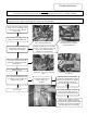
SERVICE PROCEDURE PDV24-V Main Burner & Pilot Removal and Inspection WARNING Water Heater components may be HOT when performing the following steps in this procedure. Take necessary precaution to prevent personal injury. PDV (S&T) MODELS Step 13: Pull pilot wires through burner box Step 14: Slide out burner assembly Step 15: To remove pilot, remove pilot bracket screws Step 16: Slide pilot assembly to back of burner rack Step 17: Pilot removal for servicing.
SERVICE PROCEDURE PDV24-V Main Burner & Pilot Removal and Inspection WARNING Water Heater components may be HOT when performing the following steps in this procedure. Take necessary precaution to prevent personal injury. INDUCED DRAFT MODELS Gas Valve Control Knob Main Burner Removal Burner Rack Mounting Screw Gas Valve Wire Leads Step 1. Disconnect (un-plug) water heater from electrical supply. Step 2. Turn “OFF” gas supply to water heater. Step 3.
SERVICE PROCEDURE PDV24-V Main Burner & Pilot Removal and Inspection PDV (S&T) AND INDUCED DRAFT MODELS Pilot Shield Pilot Burner Removal Step 1. With burner rack removed from heater, disconnect pilot tube connection from gas valve Step 2. Remove the two pilot burner mounting screws securing the pilot and pilot shield in place. Step 3. Remove pilot shield and pilot from burner rack. Step 4. To install pilot burner and pilot shield, reverse above procedure. Be sure to reconnect green ground wire.
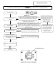
SERVICE PROCEDURE PDV24-VI Control Board Replacement DANGER 120 volt exposure. To avoid personal injury, unplug while performing this procedure. Slots in control panel Depress plastic tabs Unhook tabs from control panel slots Control board replacement Step 2. Tilt control panel to the right and slide control hook tabs from slots in control panel. Step 1. Depress left plastic tabs and pull out from slots in control panel Step 3. Unplug wire connections from board and replace.
SERVICE PROCEDURE PDV24-VII Flue Baffle Removal, Inspection WARNING Heater components may be HOT when performing the following steps in this procedure. Take necessary precaution to prevent personal injury. Step 1. Disconnect (unplug) water heater from electrical supply. Step 2. Turn “OFF” water supply to water heater. Step 3. Open a near by hot water faucet to relieve tank pressure. Step 4. Connect hose to drain valve of water heater and route to an open drain.
SERVICE PROCEDURE PDV24-VIII Anode Removal and Inspection WARNING Water Heater components may be HOT when performing the following steps in this procedure. Take necessary precaution to prevent personal injury. Step 1. Disconnect (unplug) water heater from electrical supply. Step 2. Turn “OFF” water supply to water heater. Step 3. Open a near by hot water faucet to relieve tank pressure. Step 4. Connect hose to drain valve of water heater and route to an open drain.
Generic Parts List PDV-S 1A. Vent Kit 2A. Vent Elbow 3A. Intake Terminal 4A. Vent Reducer 5A. PVC Pipe 6A. Blower Vent Adaptor 7A. Blower Receptacle Gasket 8A. Blower 9A. Temperature Switch 10A. Blower Intake Gasket 11A. Blower Mounting Flange 12A. ¼-20 Hex Nut 13A. Collector to Blower Transition 14A. Air Intake Assembly 15A. Utility Cover 16A. Air Intake Pipe 17A. Cover Rear Boot 18A. Combustion Box Boot 19A. Blower Escutcheon 20A. Blower Hose Barb 21A. Air Inlet 22A. Vent Orifice 23A.
Generic Parts List PDV S 1B. Gas Valve Assembly 2B. Burner Assembly 3B. Burner Rack 4B. Burner Tube 5B. Burner Shroud 6B. Burner Draft Panel 7B. Burner Support 8B. Aluminum Tubing 9B. Pilot Shield 10B. Pilot Orifice 11B. Pilot Assembly 12B. Street Elbow 13B. Gas Valve 14B. Aluminum Tubing 15B. Nipple Close 16B. Union 17B. Nipple 18B. Combustion Box Flange 19B. Flange Gasket 20B. Manifold 21B.
Generic Parts List PDV-S 1C. Control Box Assembly 2C. Control Box Cover Assembly 3C. Honeywell Display 4C. Control Box Cover 5C. Integrated Control Board 6C. Control Box Panel 7C. Power On/Off Switch 8C. Pan Head Screw w/adh. 9C. Pan Head Screw #8-18 10C. Transformer 11C. Strain Relief Bushing ½" 12C. Strain Relief Bushing 7/8" 13C. Snap-In-Bushing 7/8" 14C. Power Cord Wiring Harness 15C. Display Control Wiring Harness 16C. Display Cover Wiring Harness 17C. Primary Transformer Wiring Harness 18C.
Generic Parts List PDV-T 1A. ASSE Approved Mixing Valve 2A. Vent Clamp 3A. Blower Vent Adapter 4A. Combustion Box Cover 5A. Wire Raceway 7A. Blower Receptacle Gasket 8A. Blower 9A. Temperature Switch 10A. Blower Intake Gasket 11A. Blower Mounting Flange 12A. ¼-20 Hex Nut 13A. Collector to Blower Transition 15A. Utility Cover 16A. Air Intake Pipe 18A. Combustion Box Boot 19A. Blower Escutcheon 20A. Blower Hose Barb 24A. Cold Water Inlet Dip Tube 25A. Hot Water Outlet Nipple 26A. Pressure Switch Cover 27A.
Generic Parts List PDV T 1B. Burner Assembly 2B. Burner Rack 3B. Burner Tube 4B. Burner Draft Panel 5B. Burner Support 6B. Aluminum Tubing 7B. Pilot Shield 8B. Pilot Orifice 9B. Pilot Assembly 10B. Manifold 11B. Main Burner Orifice 12B. Gas Valve Assembly 13B. Nipple 14B. Street Elbow 15B. Union 16B. Nipple Close 17B. Aluminum Tubing 18B.
Generic Parts List PDV-T 1C. Control Box Assembly 2C. Control Box Cover Assembly 3C. Honeywell Display 4C. Control Box Cover 5C. Integrated Control Board 6C. Control Box Panel 7C. Power On/Off Switch 8C. Pan Head Screw w/adh. 9C. Pan Head Screw #8-18 10C. Transformer 11C. Strain Relief Bushing ½" 12C. Strain Relief Bushing 7/8" 13C. Snap-In-Bushing 7/8" 14C. Power Cord Wiring Harness 15C. Display Control Wiring Harness 16C. Display Cover Wiring Harness 17C. Primary Transformer Wiring Harness 18C.
Generic Parts List INDUCED DRAFT MODELS 1A. Flue Baffle 2A. Hex Head Anode 3A. Pressure Tap Fitting 4A. 1/8" NPT Elbow 5A. Hose Barb 6A. Silicone Hose 7A. Control Box Assembly 8A. ASSE Approved Mixing Valve 9A. Blower Transistion 10A. T & P Nipple 11A. T & P Valve 12A. Hot Water Outlet Nipple 13A. Blower Flange Mount 14A. Vent Adapter 15A. Flange Gasket 16A. Blower 17A. Drain Valve 18A. Cold Water Inlet Dip Tube 19A. Cleanout Gasket 20A. Cleanout Cover (Tank) 21A. 5/16-18 Hex Screw 22A.
Generic Parts List INDUCED DRAFT MODELS 1B. Burner Assembly 2B. Burner Panel 3B. Burner Tube 4B. Burner Mounting Bracket 5B. Burner Rack 6B. Dual Gas Valve Assembly 7B. Main Burner Orifice 8B. Manifold 9B. Pilot Assembly 10B. Aluminum Tubing 11B. Pilot Draft Shield 12B. Burner Support 13B. Valve Support Bracket 14B. 1" NPT Street Elbow 15B. 1" NPT X 3-½" Nipple 16B.
Generic Parts List INDUCED DRAFT MODELS 1C. Control Box Assembly 2C. Control Box Cover Assembly 3C. Pan Head Screw #8-18 4C. Honeywell Display 5C. Control Box Cover 6C. Integrated Control Board 7C. Pan Head Screw #8-18 8C. Transformer 9C. Ground Lug 10C. Pressure Switch 11C. Power On/Off Switch 12C. Control Box Panel 13C. Secondary Transformer Wiring Harness 14C. Primary Transformer Wiring Harness 15C. Strain Relief Bushing ½" 16C, Strain Relief Bushing 7/8" 17C. Snap-In-Plug 7/8" 18C.
Glossary of Terms AC BTU/H CO CO2 DC ECO GFI GPM Hz LED NOx NPT PSI VA VAC W.C.