
Winter / Summer Optional Kit

2
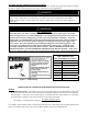
1. Unscrew and open the lower access cover. Lift the insulation and remove the twisted brown wires from the
bracket. Keep the wires from interfering and insert the thermostat (with cover) securely in the bracket. The
back of the thermostat must be in good contact against the tank wall to accurately sense the temperature.
2. Remove the wire nut from the twisted brown wires and strip the wire ends leaving ¾” of bare wire exposed.
Grasp the bottom of the grey thermostat cover and lift to gain access to the screw terminals. Connect the
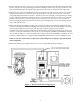
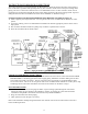
wires to the thermostat as shown in Figure 1. Gently tug each wire to the side, verifying that they are firmly
secured. Adjust the temperature setting if necessary. Lower the thermostat cover over the screw terminals
and allow the insulation to come back down over the thermostat cover. Fasten the access cover back in
place by inserting the bottom tab just inside the heater jacket and tipping up to secure the top to the outside
of the jacket with the screw.
3. Remove the Honeywell RA845A switching relay from the box and inspect for damage. Remove the cover
and secure the Honeywell RA845A switching relay to the jacket head. This Honeywell RA845A switching
relay uses the thermostat contacts to open and close the hot 120 Vac leg going to the circulator.
Feed the brown wires through the installed black rubber grommet and strip the ends leaving ¾” of bare wire
exposed. Connect the twisted brown wires to the “T” screw terminals in the Honeywell RA845A switching
relay as shown in Figure 1. Connect the 120Vac line voltage to the Honeywell RA845A switching relay and
circulator as shown in Figure 1. Apply the Honeywell RA845A switching relay cover and tighten in place.
Failure to wire the control exactly as shown may result in dangerous or improper operation for each
of the components.
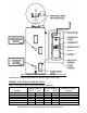
4. Remove the backing to the supplied labels and cover the existing labels as shown in Figure 2.
Figure 1 – Winter/Summer Kit Wiring Diagram