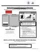
Bradford White EverHot Tankless Gas Water Heater For Exterior Installation TG-150E-N(X), TG-180E-N(X), TG-199E-N(X), TG237E-N(X) & TG-237E-N(X)A WARNING: If the information in these instructions is not followed exactly, a fire or explosion may result causing property damage, personal injury or death. Do not store or use gasoline or other flammable vapors and liquids in the vicinity of this or any other appliance WHAT TO DO IF YOU SMELL GAS Do not try to light any appliance.
SECTION I: IMPORTANT INFORMATION READ CAREFULLY This gas-fired water heater is design certified by CSA International under the American National Standard, Z21.10.3 (as indicated on the rating plate) and CAN/CGA 4.3-M (as indicated on the rating plate) available from CSA Standards Association, 5060 Spectrum Way, Mississauga, Ontario, Canada L4W 5N6. This water heater must be installed in accordance with local codes.
DANGER DO NOT store or use gasoline or other flammable, combustible, or corrosive vapors and/or liquids in the vicinity of this or any other appliance. This water heater is for outdoor installation only. Do not install indoors. This water heater is equipped with an adjustable thermostat to control water temperature. Hot water temperatures required for automatic dishwasher and laundry use can cause scald burns resulting in serious personal injury and/or death.
WARNING DO NOT tamper with or alter the water heater and/or controls. DO NOT operate water heater with jumpered or absent controls or safety devices. DO NOT operate water heater if any external part has been under water. Immediately call a qualified service technician to inspect the water heater and to replace any part of the control system including gas controls, which has been under water. DO NOT attempt to use this water heater with any gas other than the type listed on the rating plate.
WARNING Liquefied petroleum gases/propane gas is heavier than air and will remain at floor level if there is a leak. Basements, crawl spaces, closets and areas below ground level will serve as pockets for accumulation of leaking gas. Before lighting, smell all around the appliance area for gas. Be sure to smell next to the floor. IF YOU SMELL GAS: DO NOT try to light any appliance. DO NOT touch any electric switch; do not use any telephone in your building.
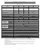
SECTION II: SPECIFICATIONS Table 1. Specifications. Model TG-150E-N(X) TG-180E-N(X) Minimum Rate Btu/h Maximum Rate Btu/h TG-199E-N(X) TG-237E-N(X) 15,000 TG-237E-N(X)A 19,000 150,000 180,000 199,000 237,000 Flow Rate (Min-Max) * 0.6-6.3 GPM (2.3-24 L/min) 0.6-7.5 GPM (2.3-28.4 L/min) 0.6-9.4 GPM (2.3-35.5 L/min) 0.6-9.8 GPM (2.3-37 L/min) Flow Rate (45ºF rise) 5.5 GPM (20.8 L/min) 6.6 GPM (25.1 L/min) 7.1 GPM (27.0 L/min) 8.5 GPM (32.
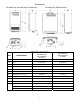
Dimensions TG-150E-N(X), TG-180E-N(X), TG-199E-N(X) TG-237E-N(X), TG-237E-N(X)A Table 2. Water Heater Dimensions. DIM DESCRIPTION TG-150E-N(X) TG-180E-N(X) TG-199E-N(X) In. (mm) TG-237E-N(X) TG-237E-N(X)A in. (mm) A Width 14 (355.6) 18 1/2 (470) B Depth 9 7/8 (249.5) 9 3/8 (230.5) C Height - Unit 22 7/8 (582) 23 5/8 (600) D Height - with brackets 25 3/8 (646.
TG-150EN(X) TG-180EN(X) TG-199EN(X) Figure 1. Graph Showing Pressure Drop v. Water Flow Rate. TG-237E-N(X) & TG-237E-N(X)A TG-199E-N(X) TG-180E-N(X) TG-150E-N(X) Figure 2. Graph Showing Water Flow Rate v. Temperature Rise.
SECTION III: INSTALLATION INSTRUCTIONS WARNING INSTALLATION OF THIS WATER HEATER REQUIRES ABILITY EQUIVALENT TO THAT OF A LICENSED PLUMBER. Plumbing, air supply, venting, gas supply and electrical work are required. DO NOT ATTEMPT TO LIGHT ANY GAS APPLIANCE IF YOU ARE NOT CERTAIN OF THE FOLLOWING: Liquefied petroleum gases/propane gas and natural gas have an odorant added by the gas supplier that aids in detection of the gas. Most people recognize this odor as a “sulfur” or “rotten egg” smell.
WARNING Residential use water heaters are suitable for potable water heating only. DO NOT use a residential use water heater for space heating or combination space heating/domestic WARNING water heating. Commercial use water heaters may be used for space heating or combination space heating/domestic water heating. Refer to the instructions for space heating in this Installation and Operation Instruction Manual. This water heater is not suitable for use in pool or spa applications.
REMOVE CARTON Move water heater to a location near where it will be installed. Carefully slide water heater out from the carton and remove all the contents. MOUNT WATER HEATER ON THE WALL This water heater must be installed outdoors. Refer to Table 3 clearances under overhangs, windows, doors, etc. Also, avoid locations where there is heavy water run-off from roofs. Determine the proper height and location for the water heater to be installed. Consider the water and gas connections.
State Regulations NOTICE BEFORE INSTALLATION Bradford White direct-vent appliance must be installed by a state qualified or licensed contractor. If you are not properly trained, you must not install this unit. IMPORTANT: In the State of Massachusetts (248CMR 4.00 & 5.
WARNING For all closet installations, follow the minimum clearances to combustibles whether the closet door is combustible or non-combustible. K VENT TERMINAL AIR SUPPLY INLET OPERABLE D E L B F B C A FIXED CLOSED G B B B A J FIXED CLOSED OPERABLE B H I M AREA WHERE TERMINAL IS NOT PERMITTED Figure 3. Installation Clearances.
Table 4. Installation Clearances.
Local codes supersede these clearances. Avoid termination locations near a dryer vent. Avoid termination locations near commercial cooking exhausts. 36" * (0.91 m) to ventilated or unventilated soffit or eve vent or to a deck or porch 12" (0.30 m) to an inside 2" (50 mm) between terminals at same level INSIDE CORNER Figure 4. Additional Installation Clearances.
High Altitude Installations The default setting for the water is 0-2,000 ft (0-610 m) with dip switch numbers 2 and 3 in the OFF position. If this water heater is installed at a higher altitude, it is necessary to modify the dip switch settings according to Table 5. Table 5. Dip Switch Settings for High Altitude Installations. 0-2000 ft (0-610 m) 2001-5200 ft (610-1585 m) 5201-7700 ft (1585-2347 m) 7701-10200 ft (2347-3109 m) Switch No. 2 OFF OFF ON ON Switch No. 3 OFF ON OFF ON Switch No.
SECTION IV: WATER CONNECTIONS WARNING Failure to install and maintain a new, listed pressure relief valve will release the manufacturer from any claim, which might result from excessive temperature and pressures. Keep clear of the pressure relief valve discharge line outlet. The discharge may be hot enough to cause scald injury. The water is under pressure and may splash. WARNING DO NOT reverse the inlet and outlet (cold and hot water) connections on the water heater.
potable water. Unions should be installed on both the hot and cold water lines for future servicing and disconnection of the water heater. Install a shut-off valve in the cold water supply line. 2. In order to service the water heater in the event the heat exchanger needs to be flushed of mineral deposits, tee fittings with shut-off valves and service connections to hoses should be installed. Also, install a shut-off valve to the hot water supply to isolate the service tee fittings.
Figure 5. Scald Warning. Table 7. Approximate scald time/temperatures.
Figure 6. Recommended Piping for a Basic Installation.
Figure 7. Recommended Piping for a Circulation Systems.
Recommended Piping for Power Failure Freeze Protection As long as electrical power and gas are supplied to the EverHot water heater, freeze protection is provided to the heat exchanger and piping inside the water heater with ambient temperatures as cold as -30F (-34C), when protected from direct wind exposure. In the event of a power failure with ambient temperatures below freezing, the water heater must be drained of all water to prevent freeze damage.
PRESSURE RELIEF VALVE WARNING Keep clear of the pressure relief valve discharge line outlet. The discharge may be hot enough to cause scald injury. The water is under pressure and may splash.
Combination Water and Space Heating Applications – Commercial Use Water Heaters Only Commercial use water heaters may be used for space heating or combination space heating/potable water heating applications, provided the following requirements and recommended piping diagrams are carefully followed. WARNING The following instructions must be carefully followed to assure safe and reliable operation of the water heater.
Note: in Massachusetts, the following must be done: Tempered potable water must meet temperatures in 248 CMR. All water piping must be insulated in accordance with 780 CMR (Massachusetts energy code). 50 feet maximum distance from water heater to space heating load (developed length). Piping loop between water heater and heating load must be in compliance with 248 CMR. All circulators must use an electronically controlled timer that activates every 6 hours for 60 seconds. Figure 9.
SECTION V: GAS CONNECTIONS WARNING Connect this water heater only to the type of gas as shown on the rating plate. Use clean black iron pipe or equivalent material approved by local codes and ordinances. Dirt and scale from the pipe can enter the gas valve and cause it to malfunction. The inlet gas line must have at least a 3 in. (7.62 cm) drip leg (sediment trap) installed as close to the water heater’s gas valve as possible.
Check the type of gas and the gas inlet pressure before connecting the EverHot® water heater to the gas supply. If the gas supply type does not match the type shown on the water heater rating plate, then DO NOT connect the water heater. Contact your Bradford White supplier for the correct water heater.
INITIAL OPERATION AND TESTING (INSTALLER ONLY) 1. Open the gas and water supply valves to the water heater. 2. Check for water and gas leaks. Use soap solution to check for gas leaks. 3. To check inlet supply pressure, remove the 1/8” NPT plug on the gas inlet supply fitting just below the bottom casing and install a barb fitting for attaching a hose to a manometer. For checking the gas manifold pressure, the plug is located just below the gas manifold connection inside the control panel. 4.
SECTION VI: ELECTRICAL CONNECTIONS WARNING Turn off or disconnect the electrical power supply to the water heater before servicing. Label all wires prior to disconnection when servicing controls. Wiring errors can cause improper and dangerous operation. Verify proper operation after servicing. All electrical wiring must be installed and grounded in accordance with local codes, or in the absence of local codes, the National Electrical Code, ANSI/NFPA 70 and/or CSA C22.2 Electrical Code.
HOT NEUTRAL FROST SENSING SWITCH 3A(FUSE) ARRESTER ANTI-FROST HEATER VARISTOR VARISTOR GND RELAY 1 IG IGNITION E SWITCHING POWER SUPPLY D PG DC170V DC12V DC12.
Figure 11. Wiring Diagram for TG-150E-N(X), TG-180E-N(X), and TG-199E-N(X) Models.
Figure 12. Wiring Diagram for TG-237E-N(X) and TG-237E-N(X)A Models.
TEMPERATURE CONTROLS The included temperature control allows the end user to set the hot water supply temperature and will display certain diagnostic codes of the water heater if there is a malfunction. All models have the option of up to four controllers that can be used to conveniently control water temperatures for bath and shower fixtures. The main control is to be at a convenient location inside the installation home or building. The adjustment range is 98-120F.
WARNING Do not adjust this water heater in any residential application above 120ºF. If this water heater is used in a commercial application where temperatures in excess of 120ºF are required, use an ASSE approved mixing device. WARNING This water heater is equipped with an energy cut out device to prevent overheating. Should overheating occur or the gas supply fails to shut off, turn off the manual gas control valve to the water heater, and call a qualified service agency.
R C O R P O R A T I °F Temperature Display O Priority P N Priority Button Priority But ton Set Temperature In Use Priority Indicator In Use Indicator Thermostat endless hot water system CAUTION: Hotter water increases the risk of scald injury. Before changing temperature setting, see instruction manual. Figure 13. Remote Control and the Description of Functions on All Controls. Residential Control, p/n 239-47806-00 Commercial Control, p/n 239-47805-00 Installation of Control(s) 1.
8. Remove the plastic cover from the PCB and electrical connections. 9. Thread the cable through the access hole at the base of the water heater and connect the wires to the control terminals on the right hand side of the PCB. REMOTE CONTROL CONNECTION TERMINALS REMOTE CONTROL CABLE CABLE CLAMP Figure 15. Illustration Showing Where to Connect Remote Control Harness. 10. Secure the control cable using the clamp provided in the control compartment. 11.
Troubleshooting – Electrical There are a number of (live) tests that are required when fault finding this product. Extreme care should be used at all times to avoid contact with energized components inside the water heater. Only trained and qualified service technicians should attempt to repair this product. Before checking for resistance readings, disconnect the power source to the unit and isolate the item from the circuit (unplug it). Table 11.
Table 17. Thermal Fuse / Overheat Switch. Wire Color Voltage Resistance Connector No. Pin Nos. Red-Red 11-13 VDC Below 1 ohms F6 H1 F6H12 Flame Rod: Place one lead of your meter to the flame rod and the other to ground. With the unit running, you should read between 5-150 VAC. Set your meter to µ amp scale and series your meter in line with the flame rod. You should read 1 µ amp or greater for proper flame circuit.
Frost Protection: This unit has frost protection heaters mounted at different points to protect the water the water heater from freezing. The heaters located on the hot water outlet line should have a resistance reading of 180207 ohms through each of these heaters. The heater located on the heat exchanger piping should have a resistance reading of 156-180 ohms, and the one located in the water flow sensor valve should have a resistance reading of 24-28 ohms.
SECTION VII: OPERATING INSTRUCTIONS WARNING Water heaters are heat-producing appliances. To avoid damage or injury there must be no materials stored against the water heater or direct vent system, and proper care must be taken to avoid unnecessary contact (especially by children) with the water heater and direct vent system.
LIGHTING INSTRUCTIONS FOR YOUR SAFETY READ BEFORE OPERATING WARNING: If you do not follow these instructions exactly, a fire or explosion may result causing property damage, personal injury or loss of life. A. This water heater does not have a Immediately call your gas supplier from a pilot. It is equipped with a direct neighbor’s phone. Follow the gas supplier’s ignition device, which automatically instructions. lights the burner.
CAUTION In climates where below freezing temperatures may occur, the water heater must be drained when power is off to the water heater to prevent freeze damage to the heat exchanger. Drain solenoids are recommended to prevent freeze damage during power failures in cold climate regions. TURNING OFF THE WATER HEATER FOR AN EXTENDED PERIOD OF TIME If the EverHot water heater is to be turned off for an extended period of time, the following steps should be taken. 1.
2. To set the desired temperature on the control, all hot water faucets must be closed. If there are remote controls installed, press the “Priority” button on the control you want to change the setting on and the “Priority” indicator light will glow. 3. Press the “H” or “C” button until the required temperature is displayed on the digital monitor. The default available water temperature range for the main control is 98-120ºF. 4. To operate the water heater, simply turn any hot water tap on.
SCALDING Figure 18. Scalding Warning. This water heater can deliver scalding temperature water at any faucet in the system. Be careful whenever using hot water to avoid scalding injury. Certain appliances, such as dishwashers and automatic clothes washers may require increased water temperature. By setting the thermostat on this water heater to obtain the increased temperature water required by these appliances, you may create the potential for scald injury.
DIAGNOSTIC CODES ON THE TEMPERATURE CONTROL DISPLAY The Bradford White EverHot tankless water heaters have the ability to monitor and display any operating faults on the control display. The diagnostic codes will display on the monitor and will assist in servicing the water heater. The following is a listing of the diagnostic codes, which may flash on the monitor in case of a malfunction with the water heater. Please quote the code displayed when calling for service.
Code Code Description Remedy 16 Over Temperature Warning 32 Outgoing Water Temperature Sensor Fault 33 Heat Exchanger Outgoing Temperature Sensor Fault 34 Combustion Air Temperature Sensor Fault 52 Modulating Solenoid Valve Signal Abnormal Combustion Fan Failure Check for restrictions in air flow around unit and vent terminal. Check for low water flow in a circulating system causing short-cycling. Check for foreign materials in combustion chamber and/or exhaust piping.
SECTION VIII: MAINTENANCE WARNING Always turn off the electrical power supply, the manual gas valve, and the manual water control valve whenever servicing this appliance. KEEP THE WATER HEATER AREA CLEAR AND FREE FROM COMBUSTIBLE MATERIALS, GASOLINE, AND OTHER FLAMMABLE VAPORS AND LIQUIDS. The EverHot water heater should be checked annually by a qualified technician. Regular maintenance will keep the water heater operating efficiently and help to assure reliable operation and a long service life. 1.
CAUTION Before manually operating the valve, make sure that a drain line has been attached to the valve to direct the discharge to an open drain. Failure to take this precaution could mean contact with extremely hot water passing out the valve during this checking operation. FLUSHING PROCEDURE FOR MINERAL SCALE REMOVAL FROM HEAT EXCHANGER The amount of calcium carbonate (minerals) released from water is in direct proportion to water temperature and usage.
Eve r Hot® Rinnai Water Heater In-line Filter V2 V1 H3 V4 V3 Cold Water Line Hot Water Line H2 H1 5 gallon pail of virgin, food grade, white vinegar (or virgin, food grade, citric acid). Circulating Pump Figure 20. Piping for Mineral Scale Flushing.
Common Troubleshooting Comments on the Operation of the EverHot® Tankless Water Heater Comment: I don’t have any hot water when I open the tap! Make sure the gas and electricity is turned on to the water heater. The temperature display should have the green light lit when a hot water tap is open and the water heater is operating. Make sure there are no diagnostic codes flashing on the display.
SECTION IX: PARTS LIST TG-150E, TG-180E, and TG-199E Models 51
801 802 806 807 808 Screw Resin Washer Screw Resin Washer Screw 4 4 2 2 4 4 4 2 2 4 52 TG-150E-X 1 2 1 1 1 1 1 2 1 1 TG-150E-N 1 2 1 1 1 1 1 2 1 1 TG-180E-X TG-199E-X Description Main Body Wall Fitting Bracket Rubber Bushing Connection Reinforcement Panel Heat Protection Plate Front Panel Front Panel Packing Main Body Packing Side Rubber Bushing Decoration Panel TG-180E-N TG-199E-N No 001 002 003 004 005 006 007 008 016 017 Quantity 1 1 2 2 1 1 1 1 1 1 1 1 1 1 2 2 1 1 1 1 1 2 1 1 1 1 1 2 1 1
TG-180E-X TG-150E-N TG-150E-X TG-199E-X Description 24 Burner Unit Assembly (LPG) 24 Burner Unit Assembly (NG) Manifold Assembly (LPG) Manifold Assembly (NG) Pressure Point Sealing Screw Combustion Chamber Front Panel Electrode FR Electrode Electrode Packing Electrode Holder Fan Motor All Assembly Combustion Chamber Bracket Air Inlet Box All Assembly Connecting Joint Joint Fixing Bracket Heat Exchanger Assembly Heat Exchanger Assembly 1 1 1 1 1 1 1 1 1 1 1 1 1 1 - 1 1 1 1 1 1 1 1 1 1 1 1 1 1 - 705 70
TG-180E-X TG-150E-N TG-150E-X TG-199E-X Description Gas Control Assembly Blind Screw 3/4 Gas Inlet 1 2 1 1 2 1 400 401 401 402 403 404 404 405 408 409 410 411 412 413 3/4 Water Inlet B Water Flow Servo & Sensor Assembly Water Flow Servo & Sensor Assembly Rectifier By-pass Servo Assembly Stop Bracket Stop Bracket Plug Band 3/4 Hot Water Outlet Stop Bracket Plug Band (small) Drain Valve Filter Plug Assembly Cover 1 1 1 1 2 1 1 1 1 1 1 1 1 1 1 1 2 1 1 1 1 1 1 1 1 1 1 1 1 1 1 1 1 1 1 700 700 701 702
TG-150E-N TG-150E-X 1 1 1 1 1 1 1 1 1 1 TG-180E-X 1 1 1 1 1 1 1 1 1 1 TG-180E-N TG-199E-X Description Frost Sensing Switch Anti Frost Heater (120V) Valve Heater (120V) Assembly Fuse Harness(FF) Power Harness Magnet Valve Harness Sensor Harness Sensor Harness Thermal Fuse Harness Sparker Harness Remote Controller Harness TG-199E-N No 712 713 715 721 722 723 724 724 725 726 729 Quantity 1 1 1 1 1 1 1 1 1 1 1 1 1 1 1 1 1 1 1 1 1 1 1 1 1 1 1 1 1 1 1 1 1 1 1 1 1 1 1 1
TG-237E Models 59
TG-237E-XA 1 1 1 2 2 2 1 1 1 1 1 1 2 4 4 2 7 10 8 TG-237E-NA Description Main Body Heat Protection Plate Front Panel Assembly Wall Fitting Bracket Front Panel Packing-Top Front Panel Packing-Side Connection Reinforcement Panel Seal Packing Rubber Bushing Reinforcement Plate Flue Outlet Packing Packing Screw Washer Screw Washer Screw Screw Quantity 1 1 1 1 1 1 2 2 2 2 2 2 1 1 1 1 1 1 1 1 1 1 1 1 2 2 4 4 4 4 2 2 7 7 10 10 8 8 1 1 1 2 2 2 1 1 1 1 1 1 2 4 4 2 7 10 8 TG-237E-X TG-237E-N No 001 002 004
TG-237E-XA 2 1 1 1 1 1 1 1 1 1 1 1 1 1 1 1 1 1 1 2 2 1 1 9 1 1 5 2 3 2 2 TG-237E-NA Description Screw Manifold Assembly (LPG) Manifold Assembly (NG) Burner Unit Assembly (LPG) Burner Unit Assembly (NG) Combustion Chamber Front Plate Electrode Flame Rod Electrode Packing Electrode Holder Electrode Sleeve Solenoid Valve Cover Heat Exchanger Complete Assembly Heat Exchanger Complete Assembly Blower Motor Fan Casing Assembly Fan Connecting Bracket Fan Connecting Packing Igniter Bracket Igniter High Tensi
TG-237E-XA 1 1 1 2 1 1 1 1 1 1 1 2 1 1 1 1 1 1 1 1 1 7 3 1 1 3 1 1 2 1 1 4 2 3 TG-237E-NA Description Cable Access Cable Access Packing Gas Connection Screw Gas Control Assembly Water Inlet Plug Band Water Filter Assembly Water Flow Servo & Sensor Assembly Rectifier Bypass-Servo Assembly Stop Bracket Water Flow Servo Cover Hot Water Outlet Plug Band Drain Valve Stop Bracket Printed Circuit Board Surge Protector Printed Circuit Board Cover-Front Printed Circuit Board Cover-Side Washer Screw Screw O-ri
TG-237E-XA 1 1 1 2 1 1 1 1 1 TG-237E-NA Description 120V Anti-Frost Heater Assembly 120V Valve Heater Assembly Thermal Fuse Harness Thermistor Frost Sensing Switch Fuse Harness Power Supply Harness Igniter Harness Sensor Harness Quantity 1 1 1 1 1 1 2 2 1 1 1 1 1 1 1 1 1 1 1 1 1 2 1 1 1 1 1 TG-237E-X TG-237E-N No 708 712 714 716 718 720 721 722 723
SECTION X: WARRANTY What does this Limited Warranty Cover? This limited warranty covers both the heat exchanger and component parts for leakage or other malfunction caused by defects in materials and/or workmanship. It applies to the original consumer purchaser and to any subsequent owner as long as the water heater remains installed at its original place of installation.
On-demand re-circulation is defined as a hot water re-circulating loop or system that utilizes existing hot and cold lines or a dedicated return line, and only activates when hot water is used. It can be activated by a push button, motion sensor, or voice activation but not by a temperature sensor. A timer added to a standard re-circulating pump is not considered as on-demand.
EverHot® Limited Warranty Registration In order to confirm Limited Warranty coverage at 12 years for Residential Applications1, complete the information below and click submit.
NOTES: 70
NOTES: 71
Ambler, PA For U.S. and Canada field service, Contact your professional installer or local Bradford White representative. Sales/800-523-2931 Fax/215-641-1670 Parts Fax/215-641-2180 Technical Support/800-334-3393 Fax/269-795-1089 Warranty/800-531-2111 Fax/269-795-1089 International: Telephone/215-641-9400 Telefax/215-641-9750 Mississauga, ON Sales/866-690-0961 905-238-0100 Fax/905-238-0105 Technical Support/800-334-3393 Email parts@bradfordwhite.com techserv@bradfordwhite.com www.bradfordwhite.