THROUGH-THE-WALL COMBINATION GAS WATER HEATER A Spanish language version of these instructions is available by contacting the company listed on the rating plate. La version espanola de estas instrucciones se puede obtener al escribirle a la fabrica cuyo nombre aparece en la placa de especificaciones. WARNING: If the information in these instructions is not followed exactly, a fire or explosion may result causing property damage, personal injury or death.
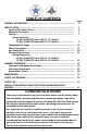
TABLE OF CONTENTS GENERAL INFORMATION................................................................................................ page 3 INSTALLATION. ................................................................................................................ Locating The Water Heater .................................................................................. Minimum Clearances............................................................................................. Venting..............
GENERAL INFORMATION This gas-fired combination water heater’s design is certified by CSA International under the American National Standard Z21.10.1 - (as indicated on the rating plate) and CSA 4.1-M - (as indicated on the rating plate). This water heater must be installed in accordance with local codes or, in the absence of local codes, the National Fuel Gas Code, ANSI Z223.1-Latest Edition) and/or in Canada CAN/CGA B149 Installation Codes (Latest Editions).
General Information continued- A sacrificial anode is used to extend tank life. The removal of this anode, for any reason, will nullify the warranty. In areas where water is unusually active, an odor may occur at the hot water faucet due to a reaction between the sacrificial anode and the impurities in the water. If this should happen, an alternative anode may be purchased from the supplier that installed this water heater. This will minimize the odor while protecting the tank.
Installation (Locating The Water Heater) continued- Note: For California installation this water heater must be braced, anchored, or strapped to avoid falling or moving during an earthquake. See instructions for correct installation procedures. Instructions may be obtained from California Office of the State Architect, 400 P Street, Sacramento, CA 95814. Water heater corrosion and component failure can be caused by the heating and breakdown of airborne chemical vapors.
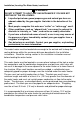
Installation (Locating The Water Heater) continued- WARNING DO NOT ATTEMPT TO LIGHT ANY GAS APPLIANCE IF YOU ARE NOT CERTAIN OF THE FOLLOWING: • Liquefied petroleum gases/propane gas and natural gas have an odorant added by the gas supplier that aids in the detection of the gas. • Most people recognize this odor as a “sulfur” or “rotten egg” smell. • Other conditions, such as “odorant fade” can cause the odorant to diminish in intensity, or ”fade”, and not be as readily detectable.
Installation (Minimum Clearances) continued- Minimum Clearances WARNING Failure to adhere to these installation and operating instructions may create a hazard to life and property and will nullify the warranty. This installation shall allow access to the front of the water heater and adequate clearance shall be provided for servicing and operating this water heater. The water heater may be installed on either a combustible or non-combustible floor.
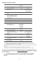
Installation (Venting) continuedCanadian Installations 1 US Installations 2 Clearance above grade, veranda, porch, deck or balcony Clearance to widow or door that may be opened 12 inches (30 cm) 12 inches (30 cm) *b *b *b E= Clearance to permanently closed widow Vertical clearance to ventilated soffit located above the terminal within a horizontal distance of 2 feet (61 cm) from the center line of the terminal Clearance to unventilated soffit 12 inches (30 cm) 4 feet (1.
2. 3. 4. Do not terminate the exhaust vent terminal where condensate or vapor could cause damage or could be detrimental to the operation of regulators, relief valves, or other equipment. Do not terminate the exhaust vent terminal over public area or walkways where condensate or vapor can cause nuisance or hazard. The vent shall terminate a minimum of 12 inches above expected snowfall level to prevent blockage of vent termination.
Installation (Venting) continuedVent pipes serving power vented appliances are classified by building codes as “vent connectors”. Required clearances from combustible materials must be provided in accordance with information in this manual under LOCATION OF WATER HEATER and CLEARANCES, and with National Fuel Gas Code and local codes. Part I - Venting Specifications for: 48 Gallon, 65,000 BTU input (189.3 L, 19.1 kW/Hr) 75 Gallon, 75,000 BTU input (283.9 L, 22.
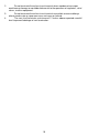
Installation (Venting) continued- TABLE 2-VENT CONNECTOR LENGTHS FOR 4” (10.1 cm) DIAMETER PVC Terminating # of 90° Elbows Maximum Minimum (excluding vent Length Length terminal) Through the Wall 1 70 ft (21.5 m) 2 ft (.6 m) Through the Wall 2 65 ft (20 m) 3 ft (.9 m) Through the Wall 3 60 ft (18.5 m) 5 ft (1.5 m) Through the Wall 4 55 ft (17 m) 8 ft (2.4 m) Through the Wall 5 50 ft (15 m) 12 ft (3.5 m) Through the Roof 1 70 ft (21.5 m) 2 ft (.6 m) Through the Roof 2 65 ft (20 m) 3 ft (.
Installation (Venting) continued- IMPORTANT All of the Venting connections must be leak checked with a soap solution upon initial start up of the water heater. Any leaks shall be repaired before continuing operation of the water heater. NOTE: ABS or CPVC pipes may be substituted for PVC pipe. Do not mix ABS and PVC pipe in the same installation. THROUGH THE WALL VENTING: Cut a 3 1/2 in. (8.9 cm) diameter hole in the wall at the point where the vent connector is going to pass through the wall.
Installation (Venting) continued- THROUGH THE ROOF VENTING: (VERTICAL VENTING) Cut the necessary holes through the roof and ceiling and install the vent connector as shown in Figure 4A. Make sure that the installation meets the local codes and/or The National Fuel Gas Code ANSI Z223.1 (Latest Edition) or CGA/CAN B149 Installation Code. Installations having long vertical runs through attics or long horizontal runs through unheated crawl spaces may accumulate condensate.
Installation (Venting) continued- THROUGH THE WALL VENTING WITH LOW GROUND CLEARANCE: When venting cannot exit through the wall at a height greater than or equal to 12” (30.5 cm) from the ground, then the installation shall be modified as shown below (see Figure 5). Refer to Table 3 for maximum venting lengths using 3” (7.6 cm) PVC or Table 4 for maximum lengths using 4” (10.1 cm) PVC.
Installation (Venting) continued- TABLE 3 3” (7.6 cm) PVC VENT CONNECTOR LENGTHS FROM INSIDE WALL FOR LOW GROUND CLEARANCE INSTALLATIONS Terminating # of Maximum Minimum Elbows Length Length (2) 90° Elbows with (1) 90° Elbow 1 30 ft (9 m) 5 ft (1.5 m) (2) 90° Elbows with (1) 90° Elbow 2 25 ft (7.6 m) 6 ft (2 m) (2) 90° Elbows with (1) 90° Elbow 3 20 ft (6.1 m) 8 ft (2.5 m) (2) 90° Elbows with (1) 90° Elbow 4 15 ft (4.6 m) 10 ft (3 m) TABLE 4 4” (10.
Combustion Air Supply WARNING Liquefied petroleum gases/propane gas are heavier than air and will remain at floor level if there is a leak. Basements, crawl spaces, closets and areas below ground level will serve as pockets for accumulation of leaking gas. Before lighting, smell all around the appliance area for gas. Be sure to smell next to the floor. IF YOU SMELL GAS: • Do not try to light any appliance. • Do not touch any electric switch; do not use any telephone in your building.
Installation (Combustion Air Supply) continued- All Air From Inside the Building: The confined space shall be provided with two permanent openings communicating directly with an additional room(s) of sufficient volume so that the combined volume of all spaces meets the criteria for an unconfined space. The total input of all gas utilization equipment installed in the combined space shall be considered in making this determination.
Water Connections Note: BEFORE PROCEEDING WITH THE INSTALLATION, CLOSE THE MAIN WATER SUPPLY VALVE. After shutting off the main water supply, open a faucet to relieve the water line pressure to prevent any water from leaking out of the pipes while making the water connections to the water heater. After the pressure has been relieved, close the faucet. The COLD water inlet and HOT water outlet are identified on the top of the water heater.
WARNING For protection against excessive temperatures and pressure, install temperature and pressure protective equipment required by local codes, but not less than a combination temperature and pressure relief valve certified by a nationally recognized testing laboratory that maintains periodic inspection of production of listed equipment or materials as meeting the requirements of the Standard for Relief Valves and Automatic Gas Shutoff Devices for Hot Water Supply Systems, ANS Z21.
Installation (Water Connections) continued- WARNING Hydrogen gas can be produced in an operating water heater that has not had water drawn from the tank for a long period of time (generally two weeks or more). Hydrogen gas is extremely flammable. To prevent the possibility of injury under these conditions, we recommend the hot water faucet to be open for several minutes at the kitchen sink before you use any electrical appliance which is connected to the hot water system.
Gas Connections The gas supply lines must meet all requirements of the National Fuel Gas Code (ANSI Z223.1-Latest Edition), or in Canada CAN/CGA B149.1 Natural Gas Installation Code (Latest Edition) or CAN/CGA B149.2 Propane Installation Code (Latest Edition). The minimum permissible gas supply pressure for the purpose of input adjustment is one (1.0) inch (0.25 kPa) water column above the operating manifold pressure. See the rating plate and gas valve for the manifold pressure and gas type.
become wet, they must be thoroughly dried before attempting to operate the water heater.
Electrical Connections All electrical wiring and connections shall be in accordance with the National Electric Code ANSI/NFPA No. 70 (latest edition), or the Canadian Electrical Code C22.1 (latest edition) and any local codes which may apply. The water heater shall be electrically grounded. If a flexible line cord and plug is permitted by local code, then provide a (3) three wire grounding type receptacle within 6 feet (1.9 m) of the water heater and use the flexible cord provided.
Electrical Connections (Figure 6) continued- Figure 6 25
GENERAL OPERATION WARNING Water heaters are heat producing appliances. To avoid damage or injury there shall be no materials stored against the water heater or vent-air intake system, and proper care shall be taken to avoid unnecessary contact (especially by children) with the water heater and vent-air intake system.
General Operation continued- 27
Thermostat Adjustment CAUTION Before adjusting thermostat(s), turn off power supply to the water heater. The thermostat dial is adjusted to its lowest temperature position when shipped from the factory. When adjusting the thermostat, it should be remembered that lower temperature settings are more energy efficient. The thermostat cover, on the right side of the gas valve, shall be removed when the thermostat is adjusted.
Burner Flame Check Cast Iron Burner: At the time of installation and at periodic intervals (not more than 6 months), a visual check of the main burner and pilot flames should be made to determine if they are burning properly. For ideal operation, the gas and air must be properly proportioned. The proper air-gas mixture is obtained by adjusting the air shutter on the mixer face of the main burner (See Figure 8).
MAINTENANCE WARNING Water heaters are heat producing appliances. To avoid damage or injury there shall be no materials stored against the water heater or vent-air intake system, and proper care shall be taken to avoid unnecessary contact (especially by children) with the water heater and vent-air intake system.
Maintenance continued- 5. Annually remove the inner door and main burner assembly to clean orifices and related parts of any dirt or other foreign material. Inspect the burner ports for obstructions or debris and clean with a wire brush as needed. Wire brush and/or vacuum clean the combustion chamber as needed to remove scale deposits and debris. NOTE: It is imperative for proper operation of the water heater that the inner door be replaced in the original location.
Maintenance (continued)- CAUTION FOR YOUR SAFETY. DO NOT ATTEMPT REPAIR OF COMBINATION GAS CONTROL, BURNERS OR GAS PIPING. REFER REPAIRS TO A QUALIFIED SERVICE TECHNICIAN. Contact your supplier or plumbing professional for replacement parts or contact the company at the address given on the rating plate of the water heater. Provide the part name, model and serial numbers of the water heater when ordering parts.
PARTS LIST DRAWING 33
PARTS LIST PART NAME AND DESCRIPTION 1. Blower Assembly 11. Diptube – Nipple 2. Temperature Switch 12. Anode – Nipple 3. Pressure Switch 13. Thermostat (Behind Cover) 4. Flue Baffle 14. T & P Relief Valve Opening 5. Honeywell Smart Valve 15. Pilot Assembly 6. Drain Valve 16. Cast Iron Burner 7. Fiberglass Insulation 17. Main Burner Orifice 8. Foam Insulation 18. Gas Feedline 9. Outer Door 19. Air Shutter (Cast Iron Only) 10. Thermostat Cover 20.