GAS-FIRED COMMERCIAL WATER HEATER (Ultra Low NOx) INSTALLATION/OPERATION MANUAL WITH TROUBLESHOOTING GUIDE WARNING If the information in these instructions is not followed exactly, a fire or explosion may result causing property damage, personal injury or death. DO NOT store or use gasoline or other flammable vapors and liquids in the vicinity of this or any other appliance. WHAT TO DO IF YOU SMELL GAS • DO NOT try to light any appliance.
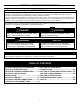
SECTION I: IMPORTANT INFORMATION READ CAREFULLY This gas-fired water heater is design certified by CSA International under the American National Standard, Z21.10.3 (as indicated on the rating plate) and CAN/CGA 4.3-M (as indicated on the rating plate) available from CSA Standards Association, 5060 Spectrum Way, Mississauga, Ontario, CANADA L4W 5N6. This water heater must be installed in accordance with local codes.
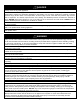
DANGER DO NOT store or use gasoline or other flammable, combustible, or corrosive vapors and/or liquids in the vicinity of this or any other appliance. This water heater is equipped with an adjustable thermostat to control water temperature. Hot water temperatures required for automatic dishwasher and laundry use can cause scald burns resulting in serious personal injury and/or death. The temperature at which injury occurs varies with the person’s age and the time of exposure.
WARNING This water heater needs fresh air for safe operation and must be installed with provisions for adequate combustion and ventilation air. Insufficient air supply will cause a recirculation of combustion products resulting in contamination that may be hazardous to life. This will result in carboning or sooting of the combustion chamber, burner, and flue tubes and creates a risk of asphyxiation.
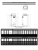
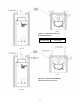
SECTION II: SPECIFICATIONS Figure 1 – Dimensional Layout Table 1 – Specifications Model Description Model Number Nominal Gal. Capacity BTU/Hr. Input US Imp. Gal Gal. UCG80H125 UCG80H199 UCG80H270 UCG100H199 UCG100H270 80 80 80 100 100 67 67 67 83 83 Dimensions (inches) GPH Recovery at Degree Rise 40°F 100°F 140°F 125,000 199,999 270,000 199,999 270,000 308 493 665 493 665 123 197 266 197 266 88 141 190 141 190 A Floor to Vent Conn. in. B Jacket Dia. in. C Vent Size in. D Floor to T&P Conn.
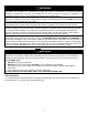
SECTION III: GENERAL INFORMATION This water heater contains the following features: Main Power On/Off Switch The front panel of this water heater has an ON/OFF switch, which has markings when the main power is turned on to indicate power to the water heater. Combustion System This water heater is equipped with a self-compensating negative pressure pre-mix combustion system. As the blower operates, air is drawn in through the air intake and into a venturi, which pulls gas from the gas valve.
Dishwashing Machine Requirements All dishwashing machines meeting the National Sanitation Foundation requirements are designed to operate with water flow pressures between 15 and 25 lbs/in2. Flow pressures above 25 lbs/in2 or below 15 lbs/in2 will result in improperly sanitized dishes. The National Sanitation Foundation also recommends circulation of 180°F (82°C) water. Where this is done, the circulation should be very gentle so that it does not cause any unnecessary turbulence inside the water heater.
SECTION IV: INSTALLATION INSTRUCTIONS WARNING INSTALLATION OF THIS WATER HEATER SHOULD BE DONE BY A TRAINED AND QUALIFIED PROFESSIONAL. PLUMBING, AIR SUPPLY, VENTING, GAS SUPPLY AND ELECTRICAL WORK ARE REQUIRED. DO NOT ATTEMPT TO LIGHT ANY GAS APPLIANCE IF YOU ARE NOT CERTAIN OF THE FOLLOWING: • Liquefied petroleum gases/propane gas and natural gas have an odorant added by the gas supplier that aids in detection of the gas. • Most people recognize this odor as a “sulfur” or “rotten egg” smell.
THIS WATER HEATER MUST BE INSTALLED INDOORS OUT OF THE WIND AND WEATHER. THIS WATER HEATER MUST NOT BE INSTALLED IN ANY LOCATION WHERE GASOLINE OR FLAMMABLE VAPORS ARE LIKELY TO BE PRESENT, UNLESS THE INSTALLATION IS SUCH TO ELIMINATE THE PROBABLE IGNITION OF GASOLINE OR FLAMMABLE VAPORS. The location of this water heater is of the utmost importance. Before installing this water heater, you should read the Installation section of these instructions.
Figure 2a – Minimum Clearance to Combustible Material Front Sides, Rear “A” 4 in. (10.2 cm) 0 in.
Remove Crate 1. Remove all banding and pry off crate sides carefully so as to not damage the water heater. 2. Carefully roll/lift the water heater from the crate base. CAUTION DO NOT drop water heater. DO NOT bump water heater jacket against floor. DO NOT bump exhaust vent pipe against crate or other objects. This will damage the heater and cause it to be inoperable or create nuisance problems. Moving the Water Heater to a Permanent Position 1.
WARNING The flue collar relief opening of the water heater and combustion air inlet must be in the same atmospheric pressure zone. Large exhaust fans in kitchens and other locations can lower the air pressure inside an enclosure and interfere with the proper operation and venting of the water heater. In these cases, the water heater should be installed in a separate room with the combustion and ventilation air supplied directly from outdoors as previously described. Unconfined Space 1.
SECTION V: VENTING WARNING The venting system must be installed properly following all local codes or in the absence of local codes, the latest edition of the National Fuel Gas Code (ANSI Z223.1- latest edition), or in Canada, The Natural Gas Installation Code (B149.1-00 latest edition) or CAN/CGA B149.2 Propane Installation Code (Latest Edition). Failure to properly install the venting system could result in property damage, personal injury, or death.
Optional Intake Venting DANGER The venting instructions must be followed to avoid restricted combustion or recirculation of flue gases. Such conditions cause sooting or risks of fire and asphyxiation. NOTICE Before beginning installation of any vent pipe, read the vent pipe manufacturer’s installation instructions. DO NOT install the water heater in any location where the ambient temperature may fall below freezing. Water heater must be protected from freezing downdrafts during shutdown periods.
Approved Intake Venting Materials For installations in the US only • PVC Sch. 40 (ASTM D-1785, ULC 1738, ULC S636) • DWV PVC Sch. 40 (ASTM-D2665) • CPVC Sch. 40 (ASTM-F441, ASTM-D2846, ULC S636) • Polypropylene (UL 1738, ULC S636) • ABS Sch. 40 DWV (ASTM D2661) For installations in CANADA • ULC S636 approved Sch.
Figure 3 – Intake Vent Terminal Clearances (Referencing Other Appliance Venting Locations) A= B= Canadian Installations1 US Installations2 Clearance above grade, veranda, porch, deck or balcony 12 inches (30 cm) 12 inches (30 cm) Clearance to window or door that may be opened 6 in (15cm) for appliances ≤10,000 Btuh (3kW); 12 in (30 cm) for appliances >10,000 Btuh (3kW) and ≤100,000 Btuh (30kW); 36 in (91 cm) for appliances >100,000 Btuh (30 kW) 4 feet (1.
Clearance to combustibles for all intake venting pipes and terminals For installations in the CANADA Refer to vent pipe and terminal manufacturer’s installation instructions for clearances to combustibles DO NOT place insulation or other materials in the required clearance spaces between the venting to combustible material unless otherwise specified.
Vertical Installation Vertical venting system must be supported every 5 ft (1.5 m) of vertical run and every 3 ft (.92 m) of horizontal run of vent pipe length. CAUTION Failure to properly support the vent piping with hangers and clamps may result in damage to the water heater or venting system. Figure 5 – Typical Vertical Intake Vent System Installation Through the Wall Venting with Low Ground Clearance When venting cannot exit through the wall at a height greater than or equal to 12 in (30.
Maximum Vent Length Table 2 – Maximum Intake Vent Length Model Number UCG100H199 UCG100H270 UCG80H125 UCG80H199 UCG80H270 Max 2” Vent Length (feet) 20 20 20 20 20 Max 3" Vent Length (feet) 50 50 50 50 50 Max 4" Vent Length (feet) 75 75 75 75 75 Determining Required Vent Length 1. 2. 3. 4. Determine the total length of straight vent pipe (in feet) required for the intake. Add 5 ft (1.52 m) of venting for every 90° elbow. Add 2 ½ ft (.76 m) of venting for every 45° elbow.
Vent Pipe Preparation WARNING DO NOT attempt to start this water heater until vent pipe solvent fumes completely clear from the room and inside the vent piping. Vent Pipe Preparation and Joining Most failures in vent systems result from improper preparation and joining of pipe and fittings. The guidelines below must be followed when installing the venting system.
SECTION VI: WATER CONNECTIONS NOTE: BEFORE PROCEEDING WITH THE INSTALLATION, CLOSE THE MAIN WATER SUPPLY VALVE. CAUTION If sweat fittings are to be used, DO NOT apply heat to the nipples on the side of the water heater. Sweat the tubing to the adapter before fitting the adapter to the water heater connections. It is imperative that heat is NOT applied to the nipples containing a plastic liner.
Alternate Space Heating Water Connections DANGER Toxic chemicals, such as those used for boiler treatment, must NOT be introduced into potable water used for space heating. This water heater must NOT be connected to an existing heating system or component(s) previously used with a non-potable water heating appliance. All piping components connected to this water heater for space heating applications must be suitable for use with potable water.
Figure 14 – Typical Plumbing Schematic for Zoned Heating SECTION VII: GAS CONNECTIONS The gas supply lines must meet all requirements of the National Fuel Gas Code (ANSI Z223.1-Latest Edition), or in Canada CAN/CGA B149.1 Natural Gas Installation Code (Latest Edition) or CAN/CGA B 149.2 Propane Installation Code (Latest Edition). The maximum permissible gas supply pressure is 14 in (3.5 kPa) W.C. for natural and propane gas. 1. Connect this water heater only to the type of gas as shown on the rating plate.
3. While checking for leaks care must be taken to prevent solution from contacting the electrical connections at the control. If electrical connections at the control become wet, they must be thoroughly dried before attempting to operate the water heater. Gas Meter Size – Natural Gases Only Be sure that the gas meter has sufficient capacity to supply the full rated gas input of the water heater as well as the requirements of all other gas fired equipment supplied by the meter.
SECTION VIII: ELECTRICAL CONNECTIONS WARNING Turn OFF or disconnect the electrical power supply to the water heater before servicing. Label all wires prior to disconnection when servicing controls. Wiring errors can cause improper and dangerous operation. Verify proper operation after servicing. All electrical wiring must be installed and grounded in accordance with local codes, or in the absence of local codes, the National Electrical Code, ANSI/NFPA 70 and/or CSA C22.2 Electrical Code.
SECTION IX: OPERATING INSTRUCTIONS WARNING Water heaters are heat-producing appliances. To avoid damage or injury there must be no materials stored against the water heater or vent system, and proper care must be taken to avoid unnecessary contact (especially by children) with the water heater and vent system.
Lighting and Shutdown Instructions Figure 16 – Lighting Instruction Label 27
Combustion Air/Gas Ratio This water heater is factory equipped with a gas valve/air mixing venturi system designed and set to maintain appropriate combustion excess air level (air/gas ratio) under normal operating conditions. When the excess air level is adjusted, an accurate and recently calibrated combustion gas analyzer, which correctly measures carbon monoxide (CO) and carbon dioxide (CO2) levels in the exhaust gas, as well as an accurate gas pressure manometer, are mandatory.
The water heater temperature setting is adjusted by using the control display mounted to the front of the water heater. The water heater thermostat is set at the lowest setpoint of 70F (21.1C) when shipped from the factory. The control display shows the temperature setpoint in degrees Fahrenheit (F) or degrees Celsius (C), and the status of the water heater (“Idle” or “Heating”). If the water heater is functioning normally, the display will also show “Operational”.
Display Control Shown flashing in display only when temp is adjusted Water Heater Display and Control Buttons Sequence of operation Indicator Reads "Idle” or “Heating" Status Indicator Read "Operational" or "Service Needed" Temperature Up Button °F setpoint idle Status Operational SELECT SET Temperature Setpoint in Degrees F or Degrees C Range: 70° - Max °F Range: 21° - Max °C Temperature Down Button Set button Select button To Increase Setpoint Temperature Step 1: Depress and hold “Temperature Up
Step 3: Press “SET” button for new setting to take effect immediately. “Setpoint” will stop flashing. If the “SET” button is not pressed, the new temperature setting will take effect in approximately 10 seconds.
Step 3: Press “SET” button for new setting to take effect immediately. The setpoint will stop flashing. If the “SET” button is not pressed, the new temperature setting will take effect in approximately 10 seconds. "Setpoint" flashes for 10 seconds setpoint °F idle Status Operational SELECT SET Press SET for setting to take effect immediately Step 3 To Change Temperature Format in Display from F to C or ˚C to ˚F: Step 1: Press “SELECT” button until “F/C” is displayed.
Step 3a: Press “Temperature Up” button to change temperature format to C. Changes to "°C" °C °F/°C idle Status Operational SELECT SET “°F/°C” Flashes Step 3a Step 3b: Press “Temperature Down” button to change temperature format to F. Changes to "°F" “°F/°C” Flashes °F °F/°C idle Status Operational SELECT SET Step 3b Step 4: Press “SET” button to confirm ˚F or ˚C format. “F/C” will stop flashing. Setpoint display will appear in the format selected (˚F or ˚C) in 10 seconds.
Step 5: Pressing “SELECT” button will return display to setpoint in format selected (˚F or ˚C) immediately. Setpoint shown in °F °F idle Status Operational SELECT SET Press select Step 5 An automatic gas shut-off device (ECO) is incorporated in the sensor and control board which will shut off all gas supply to the burner if the water heater temperature exceeds 200°F (93°C).
SECTION X: MAINTENANCE DANGER DO NOT attempt to repair gas valve. DO NOT attempt to repair ignition module. DO NOT attempt to repair venturi. DO NOT attempt to repair thermostat board. DO NOT attempt to repair transformer. DO NOT attempt to repair flow switch.
Maintenance Schedule Following are the instructions for performing some of the recommended maintenance. Unit inspection and adjustment should only be performed by a qualified technician.
Sediment and Lime Scale Removal Waterborne impurities consist of the particles of soil and sand, which settle out and form a layer of sediment on the bottom of the tank. The amount of calcium carbonate (lime) released from water is in direct proportion to water temperature and usage. The higher the water temperature or water usage, the more lime deposits are dropped out of the water. This is the lime scale which forms in pipes, water heaters, and on cooking utensils.
Temperature and Pressure Relief Valve At least twice a year, the temperature and pressure relief valve should be checked to ensure that it is in operating condition. To check the relief valve, lift the lever at the end of the valve several times. The valve should seat properly and operate freely. If water does not flow, remove and inspect for obstructions or corrosion. Replace with a new valve of the recommended size as necessary.
SECTION XI: SERVICE AND TROUBLESHOOTING GUIDE Sequence of Operations 1. When the tank temperature drops below the temperature setpoint on the display, the control sends power to the combustion blower for a 30 second pre-purge period, circulator turns on and damper opens. 2. At the end of the pre-purge period, the control sends high voltage through the spark cable to the spark rod to spark to the burner. The gas valve also opens.
Additional Display Features Accessing Diagnostic Mode on the Water Heater Display (FOR SERVICE PERSONNEL ONLY) The display has a “Service Mode” for changing the maximum setpoint and accessing information in aiding servicing of the water heater. This procedure is for service and installation personnel only. To enter the Service Mode, follow the steps illustrated below: WARNING The following procedure is for service and installation personnel only.
The following is the sequence of modes available in “Service Mode” by pressing the “Select” button: Error Code Number (Display/Reset). This is only shown if there is an operating error in the “User Mode”. Error Code Shown in Water Heater Display Status Service Needed SELECT Lockout RESET “Max Setpoint” value in Water Heater Display 1. Max Setpoint (Display/Change) Max Setpoint °F idle Status Operational SET SELECT 2. Water Temperature Sensor Reading.
3. Flame Current of Pilot Flame Sensor (Displays only in the Heating Cycle) µA Flame Current Heating Status Operational SELECT 4. Setpoint (Display/Change) SET setpoint °F idle Status Operational SET SELECT 5.
6. Differential (Display only – shows the differential of the thermostat) °F Differential idle Status Operational SELECT SET 7. Software Version (Display only) Soft idle Status Operational SELECT SET 8. Error Code History (Displays if there are present error codes or up to 10 previous error codes). Water Heater Display will show -- if there are no error codes.
To change the Maximum Setpoint Limit (Max Setpoint) for the temperature setpoint: WARNING Setting the water temperature to the maximum set point can result in scalding hot water delivered to the faucets. It is highly recommended that the maximum setpoint be adjusted to the lowest temperature possible for the needs of the installation. See following section to change the maximum setpoint limit (max setpoint).
Step 3: Press the “UP” or “DOWN” buttons to change the maximum setpoint value. This will limit the maximum setpoint the user can select. Note: The maximum setpoint is approximately 180˚F (82˚C). "Max Setpoint" continues to flash while making adjustments °F Max Setpoint idle Status Operational SET SELECT Step 4: Press “Set” button to confirm new “Max Setpoint” value and stop setting mode.
Display of Water Temperature: Step 1: In Service Mode, Press the “Select” button until “Water Temp” is displayed in the upper right section of the water heater display. This is the reading for the tank sensor. °F Water Temp idle Status Operational SET SELECT To Display Flame Sense Current of the Pilot Flame Sensor: The pilot flame sense current is available only when the burners are in operation. Step 1: Make sure the status displays “Heating” or draw enough hot water to start the burners.
To Display and Change Temperature Setpoint: Step 1: In “Service Mode” press the “Select” button until “Setpoint” is shown in the water heater display. setpoint °F idle Status Operational SET SELECT Step 2: Press the “Set” button to enter the setting mode. “Setpoint” will flash in the water heater display.
Step 4: To lower the temperature setpoint, press the “Temperature Down” button until the desired temperature is shown on the water heater display. "Setpoint" Flashes °F setpoint idle Status Operational SELECT SET Step 5: When the desired setpoint is reached on the water heater display, press the “Set” button to confirm the new setpoint. “Setpoint” stops flashing in the water heater display.
Step 2: Press “Set” button to change temperature format. “˚F/˚C” symbol will flash in the water heater display. "°F/°C" Flashes °F °F/°C idle Status Operational SELECT SET Step 3a: Press “Temperature Up” button to change temperature format to ˚C. Changes to "°C" "°F/°C" Flashes °C °F/°C idle Status Operational SELECT SET Step 3b: Press “Temperature Down” button to change temperature format to ˚F.
Step 4: Press “Set” button to confirm ˚F or ˚C format. ˚F/˚C will stop flashing. "°F/°C" Symbol Stops Flashing °F °F/°C idle Status Operational SELECT SET Step 5: Pressing “Select” button will return display to setpoint in format selected (˚F or ˚C) immediately.
How to reset the control from Lockout Conditions: WARNING The following procedure is for service and installation personnel only. Resetting lockout conditions without correcting the malfunction can result in a hazardous condition. If an error code is displayed (except for #4, low flame sense current), the water heater will be in a “lockout condition” with the water heater display showing the error code number and “Service Needed” in the status section of the display window.
Error Codes and Error History Display: If there is an operating problem with the water heater, an error code number will appear on the water heater display with “Service Needed” to the right of the “Status” indicator. The error code label is located below the water heater display and the following section in this Installation and Operating Instruction Manual explains the error codes with corrective actions to repair the water heater.
Step 2: Press the “Temperature Down” button to select the error code index, starting with the most recent error code “10”. Error Code Index idle Status Operational SET SELECT Step 3: Press the “Select” button to view the error code for “code 10”. If there is a number displayed, note what the number is. The label next to the water heater display will identify the code number.
Step 5: Press the “Select” button for code index #9 to view if there are any code numbers. Stored Error Code For Code Index #9 idle Status Operational SELECT SET Step 6: Continue pressing the “Temperature Down” button to change to the next error code index and press “Select” to view the error code number, if any, for that index number. Continue on to index #1, the oldest error code index.
DIAGNOSTIC ERROR CODES AND TROUBLESHOOTING PROCEDURES FOR EF MODELS WITH HONEYWELL INTEGRATED DIRECT SPARK IGNITON CONTROL SYSTEM Error Code Definition of Code Cause of Problem and Actions Taken to Correct Check power supply to the water heater. Make sure water heater is plugged in and the breaker is on. Check if there is 120 volts power supply to the LINE connections on the control board. If 120 volts is present, check for 24 volts output to SECONDARY terminals on the Control Board.
Error Code Definition of Code Cause of Problem and Actions Taken to Correct Burner flame is lost during run cycle, and then re-established on ignition cycle. Check inlet gas pressure. Is gas pressure dropping below the minimum operating pressure on the rating label after the gas valve opens? Is the gas pipe size to the water heater adequate? Check the condition of the burner. Clean or replace as needed. Check the burner flame and observe the microamp output on the run cycle.
Procedure for Checking Thermostat Sensors Set the thermostat above water temperature (See temperature adjustment section) and observe system through one (1) complete cycle. Make sure system operates as desired. To check the upper sensor assembly, compare the resistance of the sensor terminals (yellow and black lead for upper sensor) as measured by an ohmmeter to the water temperature as measured by an accurate thermometer. Thermistor resistance increases as the temperature decreases.
Contact your local plumbing supplier or plumbing professional for replacement parts or contact the company at the address displayed on the rating plater of the water heater. For faster and better service, please provide the part name, model, and serial number(s) of the water heater(s) when ordering parts. READ THE WARRANTY FOR A FULL EXPLANATION OF THE LENGTH OF TIME THAT PARTS AND THE WATER HEATER ARE WARRANTED.
NOTES 59
NOTES 60