Ultra Low NOx Atmospheric Vent Water Heaters with Direct Spark Ignition and ICON CONTROL SERVICE MANUAL Troubleshooting Guide and Instructions for Service (To be performed ONLY by qualified service providers) Models Covered by This Manual: UCG80H125(N,X) UCG(80,100)H199*(N,X)(A) UCG(80,100)H270*(N,X)(A) UCG(80,100)H399*(N,X) (*) Denotes Warranty Years Effective: February, 2021 ECO 8323 Manual 238-54146-00A REV 3/21 Save this manual for future reference
Ultra Low NOx Atmospheric Vent Water Heaters with Direct Spark Ignition Table of Contents Serial Number Breakdown……………………………………………………………………………………………...3 How to Use This Manual ................................................................................................................................. 4 Tools Required for Service ............................................................................................................................. 5 Specifications ..................................
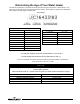
Determining the Age of Your Water Heater The first two characters of the serial number represent the year and month of manufacture. The remainder of the serial is a sequential production number, seven digits in length before December 2007 (DM), and eight digits in length after.
Introduction The Bradford White Ultra Low NOx Atmospheric Vent Water Heater is designed to deliver hot water at up to 82% thermal efficiency in a quiet running unit with a top exhaust vent connection that allows for installation in existing locations. While this unit is vented atmospherically, there is no damper required to maintain heat loss during off cycle.
Tools Required for Service Manometer: Two types available, a liquid “U” tube type or a digital (magna-helic) type. This device is used to measure gas and/or air pressures and vacuum. Multi-Meter: A digital type is strongly recommended. This device is used to measure electrical values. The meter you select must have the capability to measure volts AC, volts DC, Amps, microamps and ohms. Thermometer: Used to measure water temperature. An accurate thermometer is recommended.
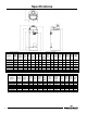
Specifications Model Description Model No. Input Rate BTU/h Storage Capacity U.S. Gallons UCG80H125 125,000 80 UCG80H199 UCG100H199 UCG80H270 199,000 199,000 80 100 270,000 80 UCG100H270 270,000 100 UCG80H399 UCG100H399 399,000 399,000 80 100 A Floor to Top of Vent 75 1/16 66 9/16 75 1/16 66 9/16 75 1/16 68 ¾ 77 ¼ Model Description Model Number Capacity (Liters) Input kW/Hr Nat. & L.P.
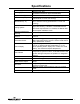
Specifications Power Supply Gas Supply Approved Gas Type Gas Pressure (Nat.) Gas Pressure (L.P.) Venting System Minimum Clearance for Servicing Maximum Water Supply Pressure Thermostat Sensor Control Display Control Board Transformer Spark Rod Igniter Flame Sensor Output Gas Valve Vent Safety Switch Blower Dedicated 120 VAC, 60 Hz, 15A GFI Minimum 3/4” NPT (schedule 40 black iron pipe recommended) Natural and L.P. Unit must match gas type supplied. 14.0” W.C. maximum static, 4.5” W.C.
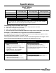
Specifications Vent Tables (Intake Only) Model Number UCG80H125 UCG(80,100)H199 UCG(80,100)H270 UCG(80,100)H399 2” Max Intake Vent Length (feet) 20 20 20 N/A 3” Max Intake Vent Length (feet) 50 50 50 75 4” Max Intake Vent Length (feet) 75 75 75 20 WARNING The UCG(80,100)H399 model is not approved for 2 inch diameter vent pipe. Venting with 2 inch pipe may result in damage to the water heater or cause an unsafe condition. DO NOT use 2 inch vent air intake pipe with UCG(80,100)H399.
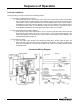
Sequence of Operation 1. Thermostat calls for heat. 2. Combustion blower starts at a 3,000 RPM “soft” start light off. 3. Blower pre-purge period of approximately 15 seconds. 4. Ignition control board runs an internal verification safety check for approximately 15 seconds. 5. Trial for ignition (approximately 5 seconds per trial, 3 trials total): a. Flame establishing period (3 seconds), gas valve opens, sparks from spark rod to burner surface to ignite the gas. b.
Sequence of Operation Lockout Conditions The system will go into lock out mode for the following reasons: 1. Error Code 110 (Ignition failure occurred) a. Control board will go into “Soft Lockout” if the main burner cannot be lit or fails to prove flame after 3 ignition trials. The water heater display indicates a lockout condition by showing an error code number 110 with “Service Needed” in the control display window. Refer to error codes in the diagnostic section of this Service Manual.
Building Management System (BMS) All water heaters with serial numbers after XA…….. (with ICON Systems) can be equipped with a gateway kit that will facilitate a Building Management System (BMS) connection to Modbus or Bacnet®. This kit is sold separately and is not factory installed. A full installation, operation, and troubleshooting manual is provided with the gateway kit.
BMS Wiring Diagram CAUTION Before beginning any Troubleshooting operations listed below, please note that the gateway kit and BMS may need to be disconnected from the heater. Please ensure this has been completed before proceeding with any troubleshooting operation that may be impacted by settings in the BMS. NOTICE The Building Management System (BMS) is only compatible with units that have SOLA controllers.
Troubleshooting System Observations WARNING Water Heater Fault: Water heater does not operate Display Error Code: Water heater display does not operate - blank display 120 volt potential exposure. Use caution making voltage checks to avoid personal injury. Check main power supply to water heater – fuse, circuit breaker, plug receptacle, line cord or wiring to water heater. CAUTION Use caution to not damage connectors when making voltage measurements or jumping terminals.
Troubleshooting WARNING CAUTION 120 volt potential exposure. Use caution making voltage checks to avoid personal injury. Use caution to not damage connectors when making voltage measurements or jumping terminals From previous page. Does combustion blower operate? Error code 67 on display. Measure voltage between black and white wires, of the 3 wire harness, at the blower (make sure the control display shows “heating” in the status mode, if not increase the setpoint).
Display Control Water Heater Display and Control Buttons To Increase Temperature Setpoint Step 1. Press and hold “Temperature Up” button until desired setpoint temperature appears on the display. Step 2. Press “DONE” button for new setting to take effect immediately. If the “DONE” button is not pressed, the new temperature setting will take effect in approximately 10 seconds.
To Decrease Temperature Setpoint Step 1. Press and hold “Temperature Down” button until desired setpoint temperature appears on the display. Step 2. Press “DONE” button for new setting to take effect immediately. If the “DONE” button is not pressed, the new temperature setting will take effect in approximately 10 seconds. To View Combustion Rate Step 1. Select Next while viewing DHW Setpoint in User Mode to access Rate screen. Rate will only be displayed while the burner is operating. Step 2.
To Change Temperature Format in Display from F to C or ˚C to ˚F Step 1. Enter “Set-Up Mode” by pressing both UP/DOWN buttons together for 3 seconds. Step 2. Use the arrows to select between °F and °C Step 3. Press done to return to main screen or timeout/change will occur in one minute. An energy cut out (ECO) is incorporated in the sensor and control board which will shut off all gas supply to the burner if the water heater temperature exceeds 207°F (93°C).
Troubleshooting Accessing Diagnostic Mode on the Water Heater Display (FOR SERVICE PERSONNEL ONLY) The display has a Diagnostic Mode to access information in aiding servicing of the water heater. This procedure is for service and installation personnel only. To enter the Diagnostic Mode, follow the steps illustrated below: WARNING The following procedure is for service and installation personnel ONLY. Resetting lockout conditions without correcting the malfunction can result in a hazardous condition.
Step 3. Press the lower right “Next” button. The display will flash and show the number of any alert codes. These are not currently used. Step 4. Press lower right “Next” button. The display will flash and show the number of any Lockout codes. If there are no lockouts, the display will show 00. If there are multiple lockout codes “Next” will scroll through them. Step 5. Press “Next”, the display will show “DHW MAX”.
Troubleshooting Step 6. Press Next, display will show “DELTA T DHW”, this is the real time temperature reading of the tank. Step 7. Press “Done” to exit Diagnostic Mode and return to the DHW setpoint in User Mode.
NOTICE The ICON control system can produce soft and hard lockouts. Soft lockouts are displayed if active and are not stored in Diagnostic Mode history. The control will periodically attempt to resume normal operation when in soft lockout conditions. If the system resumes normal operation a soft lockout will clear instantly; hard lockouts will display if active and require manual reset. Up to ten previous Hard lockouts are logged chronologically (newest first) in Diagnostic Mode history.
Error Code Definition of Code Cause of Problem and Actions Taken to Correct • Appears after alert 172, defined below. Check the water temperature sensor wire harness from the sensor to the control module. Make sure there are no loose connections to the control plug. Check the resistance reading from each of the outside wires to the center (common) wire. Measure the tank temperature and compare with the chart below. If the ohm readings are not fairly close, replace the sensor.
Service Procedure I: Thermostat Circuit Testing and Replacement WARNING IMPORTANT NOTE: This procedure assumes a cool tank. 120 volt potential exposure. Use caution making voltage checks to avoid personal injury. Condition: Water heater not operating. Display shows error code “93” (sensor reading faulty) CAUTION Unplug or disconnect electrical power to the water heater. Use caution to not damage connectors when making voltage measurements or jumping terminals.
Service Procedure I: Thermostat Circuit Testing and Replacement Condition: Water heater not operating. Display shows error code 80 high water temperature (over 207°F (92.7°C)) (continued from previous page). WARNING DO NOT operate water heater without verifying that the overheating condition has been corrected. Once cause of overheating condition has been diagnosed and corrected, the control may be reset. • • • • • Reconnect and switch on power to the water heater.
Service Procedure I: Thermostat Circuit Testing and Replacement Thermostat Sensor (Thermister) Replacement Procedure 1. Position main power switch to OFF. 2. Disconnect (unplug) water heater from 120 volt power source. 3. Unlatch and remove the top surround cover from top of heater. WARNING 120 volt potential exposure. Isolate the appliance and reconfirm power is disconnected using a multi-meter. 4. Disconnect the temperature sensor from control (see images below). 5.
Service Procedure I: Thermostat Circuit Testing and Replacement APPENDIX-A Sensor Resistance at Various Temperatures Be careful when making voltage measurements or jumping terminals not to damage or deform connectors or connector pins. Draw water from the temperature and pressure relief valve. Compare temperature with temperature ohms chart below. Example: If the temperature is 84°F, then the resistance through the sensor would be 8449 (see shaded area).
Service Procedure II: Combustion System Testing and Replacement Observe burner operation through the sight glass located on the combustion insert mounting flange. Normal burner operation should ignite smoothly, without evidence of coughing or huffing upon ignition. The burner flame should be a blue flame near the burner surface in a uniform flame pattern. Occasional yellow or white streaks are normal.
Service Procedure II: Combustion System Testing and Replacement Observe burner operation through the sight glass located on the combustion insert mounting flange. Normal burner operation should ignite smoothly, without evidence of coughing or huffing upon ignition. The burner flame should be a blue flame near the burner surface in a uniform flame pattern. Occasional yellow or white streaks are normal.
Service Procedure II: Combustion System Testing and Replacement WARNING WARNING Heater components may be HOT when performing the following steps in this procedure. Take necessary precaution to prevent personal injury. 120 volt potential exposure. Isolate the appliance and reconfirm power is disconnected using a multi-meter. Combustion System Removal Procedure 1. Position main power switch to OFF. 2. Disconnect (unplug) water heater from 120 volt power source. 3. Turn OFF gas supply to water heater. 4.
Service Procedure II: Combustion System Testing and Replacement Combustion System Replacement Procedure 1. Fully inspect burner mounting insert gasket for the following: a. Tears d. Dirt or debris b. Missing material e. Other imperfections that would inhibit proper seal c. Cracks If gasket is NOT affected by any of the above, gasket replacement is not required. 2. Install the combustion assembly using new gasket or fully inspected gasket from Step 1.
Service Procedure III: Burner Tube Inspection and Replacement WARNING WARNING Heater components may be HOT when performing the following steps in this procedure. Take necessary precaution to prevent personal injury. 120 volt potential exposure. Isolate the appliance and reconfirm power is disconnected using a multi-meter. Burner Tube Removal Procedure 1. Position main power switch to OFF. 2. Disconnect (unplug) water heater from 120 volt power source. 3. Turn OFF gas supply to water heater. 4.
Service Procedure III: Burner Tube Inspection and Replacement WARNING Heater components may be HOT when performing the following steps in this procedure. Take necessary precaution to prevent personal injury. Burner Tube Inspection 1. Inspect burner tube as follows (Acotech metal fiber mesh burner). a. Outer fiber mesh should be uniform with no tears or deterioration. b. Gently squeeze burner tube, Burner tube should feel firm without any soft areas around the sides or at the bottom. c.
Service Procedure IV: Gas Valve Replacement Gas Valve Replacement Procedure WARNING 1. Position main power switch to OFF. 2. Disconnect (unplug) water heater from 120 volt power source. 120 volt potential exposure. Isolate the appliance and reconfirm power is disconnected using a multi-meter. 3. Turn OFF gas supply to water heater. 4. Unlatch and remove surround cover from top of heater. 5. From the gas valve, disconnect the gas connection, PVC venting, wire harness, and silicone tubing. 6.
Service Procedure V: Blower Testing and Replacement Does blower energize? Ensure control display shows “heating.” Raise temperature setpoint if necessary. Is collector high limit switch in normally closed position? Y Y N N Determine power source problem and correct. N Check amp draw through BLACK wire lead of blower motor. Is there .6 to 3.0 amps? N Call Technical Support.
Service Procedure V: Blower Testing and Replacement Blower Replacement Procedure WARNING 1. Position main power switch to OFF. 2. Disconnect (unplug) water heater from 120 volt power source. 3. Turn OFF gas supply to water heater. 4. Unlatch and remove surround cover from top of heater. 120 volt potential exposure. Isolate the appliance and reconfirm power is disconnected using a multi-meter. 5. Disconnect the 2 wire harnesses from blower. 6.
Service Procedure VI: Flame Sensor Testing and Replacement WARNING Flame Sensor Testing Procedure Refer to illustration below, is there a minimum of 1 µA during 1.5 second flame proving period? Y N With flame sensor disconnected from ignition module, check continuity to ground. Is there continuity to ground? Y N Remove flame sensor from water heater. Check continuity from tip of flame sensor to end of wire lead.
Service Procedure VI: Flame Sensor Testing and Replacement Flame Sensor Replacement Procedure WARNING 1. Position main power switch to OFF. 2. Disconnect (unplug) water heater from 120 volt power source. 3. Unlatch and remove surround cover from top of heater. 120 volt potential exposure. Isolate the appliance and reconfirm power is disconnected using a multi-meter. 4. Disconnect the wire lead from flame sensor. 5.
Service Procedure VII: Spark Rod Gap Adjustment and Replacement Spark Rod Gap Inspection and Adjustment 1. Remove combustion system as described Combustion System Removal Procedure, pg 27. in 2. Measure spark gap between the spark rod and burner tube. Acceptable spark gap is from 3/16" to 1/4" (see image below). 3.
Service Procedure VII: Spark Rod Gap Adjustment and Replacement Spark Rod Replacement Procedure WARNING 1. Position main power switch to OFF. 2. Disconnect (unplug) water heater from 120 volt power source. 120 volt potential exposure. Isolate the appliance and reconfirm power is disconnected using a multi-meter. 3. Unlatch and remove surround cover from the top of the water heater. 4. Disconnect wire lead from spark rod. 5.
Service Procedure VIII: Ignition Module/Control Board Replacement Control Board Replacement WARNING 1. Position main power switch to OFF. 2. Disconnect (unplug) water heater from 120 volt power source. 3. Unlatch and remove top surround cover from the top of the water heater. 120 volt potential exposure. Isolate the appliance and reconfirm power is disconnected using a multi-meter. 4. Locate the control board. 5. Carefully disconnect all wire connections from the control board.
Service Procedure IX: Blocked Vent Switch Inspection and Replacement Blocked Vent Switch Procedure Blocked vent switch should be installed on the lip of the drafthood 1. First determine if the blocked vent switch was installed correctly on the drafthood (see image to right). 2. When error code 67 is present on an ICON Control Systems Model, or error code 26 is present on an Integrated Control Model, you first must determine if there is a blocked vent condition present.
Service Procedure X: Anode Inspection and Replacement Anode Replacement Procedure WARNING 1. Position main power switch to OFF. Heater components and stored water may be HOT when performing the following steps in this procedure. Take necessary precaution to prevent personal injury. 2. Disconnect (unplug) water heater from 120 volt power source. 3. Turn OFF water supply and drain the water heater. 4. Locate (see image below) and remove anode rods from heater (1-1/16 hex socket). 5.
Service Procedure XI: Display Module Replacement WARNING Display Module Replacement 1. Position main power switch to OFF. 2. Disconnect (unplug) water heater from 120 volt power source. 120 volt potential exposure. Isolate the appliance and reconfirm power is disconnected using a multi-meter. 3. Remove 4 screws that hold the display into the enclosure (see image below). 4. After removing the screws pull the display out of the enclosure. 5. Once the display is removed, disconnect the two mating plugs. 6.
Service Procedure XII: Transformer Replacement Transformer Replacement Procedure WARNING 1. Position main power switch to OFF. 120 volt potential exposure. Isolate the appliance and reconfirm power is disconnected using a multi-meter. 2. Disconnect (unplug) water heater from 120 volt power source. 3. Unlatch and remove surround cover from top of water heater. 4.
Water Heater Installation Checklist Product Handling Carefully uncrate the heater. Move in place with a hand truck (Do NOT use the venting pipes for handles). Electrical Requirements Make sure there is 120 volts line voltage. Line voltage must be properly polarized. Adequate ground supplied to the heater. Venting Requirements All venting must stay within the required lengths and diameter (see table below). Proper support of the venting pipe is a MUST (every 5 ft (1.5 m) vertical and 3 ft (.
Water Heater Service Report Date: _______________ Service Provider: _____________________________ Model Number: _______________________________ Phone Number: _______________________________ Serial Number: Intake Venting: Intake Vent size 3”, 4” ______ Intake 45° Elbows (qty) Intake 90° Elbows (qty) ______ Exhaust Vent Size 6”,7”,8” ______ _____________________________ Length of Straight Pipe (Intake) ________ Gas Line: Gas Pressure: Venturi: Size & Material ______________ Static ____________
Glossary of Terms AC BTU/H CO CO2 DC DSI ECO GFI GPM Hz LED NOx NPT PSI RPM VA VAC W.C.