
Service Manual

7
7
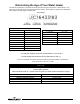
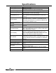
Specifications
Power Supply
Dedicated 120 VAC, 60 Hz, 15A GFI
Gas Supply
Minimum 3/4” NPT
(schedule 40 black iron pipe recommended)
Approved Gas Type
Natural and L.P. Unit must match gas type supplied.
Gas Pressure (Nat.)
14.0” W.C. maximum static, 4.5” W.C. minimum running
(recommend 7.0” W.C. min running)
Gas Pressure (L.P.)
14.0” W.C. maximum static, 11.0” minimum static, 4.5”
W.C. minimum running (recommend 7.0” W.C. min
running)
Venting System
Atmospherically vented, Type B venting system or
approved chimney. Follow the current National Fuel
Gas Code requirements or in Canada, the Natural Gas
and Propane Installation Code.
Minimum Clearance for
Servicing
16” from top, 4” from front, 0” sides and rear.
Maximum Water Supply
Pressure
150 PSI
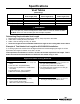
Thermostat Sensor
11,900 Ohms @ 70°F, ECO opens @ 207°F (92.7°C)
Max. Redundant sensor for ECO. Sensor inside well for
easy replacement of sensor.
Control Display
Digital display, 24 volts. temperature Range: 70-180°F
(21-82°C). Used to set tank temperature (°F or °C),
show operating status, display error codes, error code
history, limit maximum setpoint temperature.
Control Board
Operates from 24 volt from transformer. Controls tank
temperature, ignition functions, combustion blower. See
ignition timings in sequence of operation for Integrated
Control.
Transformer
120 VAC primary, 24 VAC secondary, 40 VA.
Spark Rod Igniter
0.22” nominal gap to the burner surface.
Flame Sensor Output
Minimum 1 micro amp. Typical range 5 to 30 micro
amps.
Gas Valve
Negative regulation, 24 VAC, ½” PSI max., 4.5” W.C.
minimum running inlet.
Vent Safety Switch
Normally closed, opens @ 240°F (115.5°C), manual
reset.
Blower
120 VAC, 60 Hz, 1.5-3.5 amps