
Installation Manual
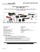


! INSTALLATION!INSTRUCTIONS!
5000-ca6.doc Page 2 of 5
1. Find an appropriate place to mount all
components
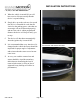
A. The Proximity sensor MUST be mounted as
close as possible to the center of the front of
the vehicle with a clear line of sight to the
curb (it is an IR sensor and so it CANNOT
be mounted behind the license plate, any
panel and or object that will obstruct its
view.) Note: the sensor must be placed
where it will not be easily struck or damaged
by road debris or so low that it will be
damaged during entry or exit out of
driveways.
B. The Speaker must be accessible to the
vehicle owner in order to allow operation of
the built-in Power switch.
C. The camera should be mounted in the center
of the vehicle to see a view of the lower
edge of the lower front fascia.
D. The Main Module must be mounted in the
cabin area where it will be easy to program
for proper operation once installed (the
program switch will NOT be used by
customer once installation and proper
programming is done and so it can be hidden
out of sight).
• 2) Installing hardware:
A. Clean the mounting surface where the sensor
will be adhered using a clean cloth and the
3M prep-pad or alcohol. \\Make sure not to
leave any residue on the surface (do NOT
tighten Allen screw completely as the sensor
will be adjusted later during programming).
B. Clean*the*mounting*su rface*where*the*
camera*will*be*adhered*using*a*clean*
cloth*and*the*3M*prep-pad*or*alcohol.
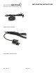
C. Connect*the*2*WHITE&wires*at*the*plug*on*
the*camera*harness*together.(If*you*do*
not*want*park*lines*to*show*from*the*
camera*the*connect*the*2*GREEN&wires*
together.)
D. Plug*the*camera*harness*into*the*chassis*
harness*and*route*the*harness*with*the*
sensor*harness*into*the*vehicle*through*
the*firewall.
E. Route the sensor harness through the
firewall into cabin area making sure to stay
away from any moving parts and away from
extreme temperature engine components.
F. Mount the Buzzer by first cleaning the
surface with either a cleaning solution or
alcohol.
G. Mount the Main Module using the supplied
cable ties making sure not to obstruct any
objects such as the steering column and or
foot petals under the steering column area
(make sure that nothing will accidentally
press the Program switch as this will de-
calibrate the unit).
H. Connect the buzzer as well as the sensor
connector to the module, leave about a 1/8
th
of an inch of slack. Use a cable tie to secure
them to the power cable (this will insure that
the connections will not come lose while
vehicle is in normal operation).
• 3) Power connection:
A. Connect the BLACK wire of the power
harness and camera harness to a good solid
ground (it is recommended to trim cable to
appropriate length).