
Owner's Manual
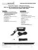


Installation Instruction Overview - Rear Vision System Aftermarket Display
2007-Current Chevy Silverado, Silverado HD; GMC Sierra, Sierra HD
(Kit Part number 9002-9560)
9560 Instruction Overview 7-2-13.doc Page 1 of 1
REQUIRED CONNECTIONS
Wire
Color
Polarity
Function
Connection
Complete Instruction
Steps
RCA
AC
Video
Aftermarket display / NAV display video IN
46
Pink
or
Red
+
Ignition
MBEC C12/ X12 Brown Connector cavity 7
47
Alternate connection: BCM X5 Brown Connector cavity 13
48
Green
+
Reverse
MBEC C11/ X11 Light Gray Connector cavity 5 OR
MBEC C10/ X10 Gray Connector cavity 8
47
Alternate connection: BCM X5 Brown Connector cavity 11
48
Black
–
Ground
Stud on left hand side of dashboard
47
• Use kit instructions to verify contents are complete. For the latest full color instructions and an installation video, please visit www.brandmotion.com
Preparation (Steps 1 thru 4 in supplied complete kit instructions)
1-2 Turn lamps, accessories, and ignition off.
3 Disconnect negative battery cable.
4 Wait one (1) minute to assure the SIR roof rail air bag system is disabled before proceeding.
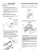
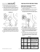
Install Camera Bezel into Tailgate (Steps 5 thru 29 in supplied complete kit instructions)
5-10 Lower tailgate to remove tailgate bezel and then remove tailgate and place on work surface.
11-17 Using the supplied Template, drill 29mm (1-1/8”) hole(s) for camera grommets at the bottom of the tailgate and pickup box.
If the pickup box already has an existing hole, remove its flange so the grommet will fit. Clean rough edges of drilled hole(s)
using a deburring tool and then apply anti corrosion coating.
18-20 Prepare the supplied Camera Bezel by transferring the vehicle’s lock cylinder or installing supplied Lock Plug.
21-24 Route the camera harness through drilled hole in tailgate. Snap Camera Bezel in place and seat grommet.
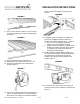
25-29 Reinstall tailgate, route the Camera Harness through the drilled pickup box hole and then seat the grommet into pickup box
hole. If present, remove rear license plate.
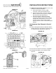
Determine Reverse Signal Location (Steps 30 thru 33 in supplied complete kit instructions)
30-31 Remove left IP outer trim cover and M-BEC cover.
32 Have an assistant set parking brake, start vehicle, and shift into Reverse. Using a digital multimeter, check for reverse signal
in Cavity 5 at Light Gray C11/X11 Connector OR Cavity 8 of Gray C10/ X10 Connector in M-BEC.
33 If reverse signal is NOT present in the C10/ X10 Connector or C11/ X11 Connector:
A. Check that bail that secures the M-BEC connectors is fully locked. Repeat Step 33.
B. If reverse signal is still not present, check Fuse Block for blown fuses. Replace any blown fuses & repeat Step 33.
C. If reverse signal is still NOT present, connection to reverse signal must be made at the BCM rather than the C10/ X10
or C11/ X11 Connector (refer to Step 48 under “Install Chassis Harness & Connect to Aftermarket/ NAV Display”).
Cut Accessory Pass Through In Front of Dash (Steps 34 thru 41 in supplied complete kit instructions)
34-36 Remove the Parking Brake release handle, knee bolster, M-BEC, and M-BEC.
37-38 Move M-BEC to access front of dash opening to locate drilling location. Drill a 25.4mm (1”) hole for grommet near existing
dimple or existing grommet.
39-41 Clean rough edges of drilled hole(s) using a deburring tool, and apply anti corrosion coating.
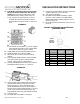
Install Chassis Harness and Connect to Aftermarket Display / NAV Display (Steps 42 thru 57 in supplied complete kit
instructions)
42 If needed, install aftermarket display/ Navigation display as per instructions.
43-45 Locate Chassis Harness from kit. Route grommet end of the Chassis Harness through drilled hole in dash and seat grommet.
46 Connect the male RCA from the supplied Chassis Harness to the camera IN on the aftermarket display/ Navigation display.
47 Splice the Green Reverse (+) Chassis Harness wire to the wire in M-BEC C11 gray connector pin 5.
47 Splice the Red or Pink Ignition (+) Chassis Harness wire to the wire in M-BEC C12 brown connector pin 7.
47 Secure the Eyelet of the black Ground (-) Chassis Harness wire to a chassis ground stud.
48 If all M-BEC connections were secure and no fuses were blown and Reverse was still not present, Reverse must
be located in the under dash BCM left of the steering wheel.
A. Splice green Reverse (+) wire of supplied Chassis Harness to wire in Brown BCM X5 Connector Cavity 11.
B. Splice pink or red Ignition (+) wire of supplied Chassis Harness to wire in Brown BCM X5 Connector Cavity 13.
49-50 Install the M-BEC into the Support Bracket and reinstall the M-BEC cover.
51-52 Route the Chassis Harness towards the rear of the vehicle and along the vehicle’s chassis harness.
53 Connect the supplied Chassis Harness to the supplied camera harness.
54-55 Secure supplied harnesses to existing harness using Wire Ties every 200mm (approx. 8”).
56 Reinstall rear license plate, if necessary.
57-58 Reinstall negative battery cable and test system.
59-60 Reinstall all previously removed interior parts.