
Owner's Manual


INSTALLATIO N (IN S TR UCTIONS(
9002-9560 Instructions 9-23-16.doc GS
6 of 7
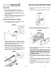
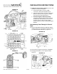
37. Relocate M-BEC up into the IP to gain access to
Front of Dash Mat Opening behind M-BEC.
38. Locate cut-out in dash Mat. Locate the dimple in the
sheet metal and then use a center punch to help
start a drill bit as close as possible to dimple. Using
a power drill and a 25.4mm (1”) hole saw, drill out
the chassis harness pass-through (2). Figure 20.
FIGURE 20
39. If this location is occupied by Trailer Brakes (&JL1)
or another Accessory, drill a new Chassis Harness
pass-through (3) between the IP Harness (1) and
Trailer Brake (2) pass-through grommets. Figure 20.
40. Clean rough edges using a deburring tool. Figure 20.
41. Apply Anti-Corrosion Coating to the opening. Figure
20.
Install Chassis Harness & Connect to
Aftermarket/ NAV Display
42. If needed, install aftermarket display/ Navigation
display as per instructions.
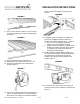
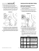
43. Locate the supplied Rear Chassis Harness with RCA.
44. Route the grommet-end of the Chassis Harness
through the Driver’s Side Wheel Housing and then
through the opening in the Front-of-Dash. Figure 21.
FIGURE 21
45. From the inside of the cab pull the Chassis Harness
through until the grommet is properly seated.
46. Connect male RCA from supplied Chassis Harness to
camera IN on the aftermarket display/ Navigation
display. In some cases a RCA extension may be
required.
47. If you located Reverse and Ignition signals in the M-
BEC connector, connect the remainder of the leads
from supplied Chassis Harness to vehicle wiring per
Chart A and proceed to Step 50. Otherwise, skip to
Step 49.
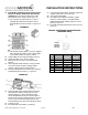
Chart A
Color
Polarity
Function
Connect to:
Green
+
Reverse
Splice to wire in M-BEC
C11/ X11 light gray
connector pin 5 OR
M-BEC C10/ X10 gray
connector pin 8
Red
or
Pink
+
Ignition
Splice to wire in M-BEC
C12/ X12 brown
connector pin 7
Black
–
Ground
Stud on left hand side of
dashboard
RCA
plug
AC
Video
Out
Monitor
.-
0
C