
Owner's Manual
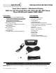


INSTALLATIO N (IN S TR UCTIONS(
9002-9560 Instructions 9-23-16.doc GS
7 of 7
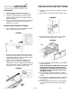
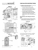
48. If all M-BEC connections were secure and no
fuses were blown and Reverse was still not
present, Reverse must be located in the under
dash BCM left of the steering wheel. Figure 15
A. Cut connector off green Reverse (+) wire of
supplied Mirror Harness and splice to wire in
Brown BCM X5 Connector Cavity 11. Figures 15
& 22.
FIGURE 22
B. Cut terminal off pink ignition (+) wire of supplied
Mirror Harness and splice to wire in Brown BCM
X5 Connector Cavity 13. Figures 15 & 22.
49. Install M-BEC into the Support Bracket. Figure 15.
50. Install the M-BEC cover onto the M-BEC.
51. Raise Truck up on a hoist to route the Chassis
Harness.
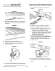
52. Route supplied Chassis Harness, working towards
rear of the vehicle, along the existing Chassis
Harness, routing away from Body Mounts.
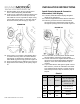
53. Connect Chassis Harness Connector (2) to Camera
Assembly Harness Connector (1). Figure 23.
FIGURE 23
54. Secure the Rear Vision Camera Harness along the
existing Chassis Harness using Wire Ties every
200mm (approx. 8”). Note: Depending on the
vehicle wheelbase there may be excess length in
the Rear Vision Camera Chassis Harness. Loop, and
secure any excess harness length with wire ties
along the Body Frame away from Mechanical areas.
55. Lower the truck.
56. Re-Install Rear License Plate, if necessary.
57. Connect the negative battery terminal. Tighten the
negative cable nut to 5 N·m (44 lb in).
58. Test system functionality.
59. Re-install the Knee Bolster Assembly. Tighten
Screws to 2 N·m (18 lb in). Re-install Parking
Brake Release Handle and Bolt, tighten to 9 N·m
(80 lb in). Figure 14.
60. Re-install Instrument Panel Outer Trim Cover. See
Figure 13.
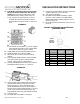
Camera and Chassis Harness Pinouts
(REFERENCE ONLY)
PIN
#
FUNCTION
CAMERA
HARNESS
COLOR
CHASSIS
HARNESS
COLOR
1
Video +
Yellow
White
2
Shield
White
Blue
3
Reverse
Brown
Green
4
Video –
Gray
Brown
5
Ground
Black
Black
6
Ignition +
Red
Red
Camera
Harness
Connector
end view
25
19