12 13
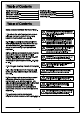
Dimension Reference 6in 15.6in-20.6in 24in 65in Hardware Included 2pcs Flat washer Wood Screww 4pcs Balanced patch 2pcs Wire Nut 3PCS Plastic clip 1pcs Expansion screw 4pcs Fan Parts Included 1 Quantity 1. Mounting Bracket 1 2. Down Rod 1+1 3. Canopy 1 4. Canopy Cover 1 5. Metal Cover 1 6. Motor 1 7. LED Module 1 8. Light Shade 1 9. Remote Control 1 ( Batteries Not Included) 10.
Exploded review 2 1 Mounting Bracket 3 Canopy 2 Canopy Cover Metal Cover Bolt Down Rod Cotter Pin 4 Motor Fan Blade 4 LED Module Fixing Blade Screws 5 Fixing LED Screws Light Shade NOTE: The illustration shown is not scale or its actual con guration may vary.Product/parts are subject to change with out notice.
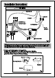
Installation Instructions Step1 MOUNTING - Take out fan motor housing. - Remove cotter pin and bolt from yoke. - Loosen jam screw in yoke until it is flush with the inside surface. - Obtain downrod, canopy and yoke cover. - Place downrod inside canopy and yoke cover. - Route wires exiting motor through yoke cover, canopy and downrod. - Insert bolt through hole in and downrod. Be careful not to damage or cut the fan wires -Tighten bolt. Secure with cotter pin through hole in the end of the bolt.
Installation Instructions Step2 MOUNTING BLADES TO MOTOR - Fix the fixed support blades on the motor in turn.
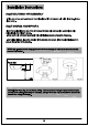
Installation Instructions Step4 INSTALL MOUNTING BRACKET - Install J-Hook through centre of outlet box and into the wooden joist. - Secure mounting bracket and rubber gaskets to metal outlet box. - Hang the safety cable onto the J-hook. Wood joist J-hook J-hook Qutlet box Safety Cable Ceiling Mounting bracket Canopy Outlet box screws Fig. 4a Step5 ELECTRICAL HOOK-UP A.Make the following wire connections to the receiver unit using the wire nuts supplied. - Connect GREEN fan wire to BARE (ground) wire.
HOW TO OPERATE CEILING FAN BY REMOTE CONTROL 1 2 2 1 2 3 2 6 4 2 AAA 1.5V (Batteries not included) 2 5 2 8 1 Switch indicator 2 Speed Controller Fan 7 3 Shutdown 7 4 Fan Reverse 5 Natural wind 6 Lamp Switch 7 Timer 8 Battery For Switch AAA ( 1 . 5V ) (Batteries not included) 3 4 7 7 1H 2H 4H 8H 5 6 Actual use shall be subject to the real product Learning method of remote control: Power on the receiver,press the ringing from the loudspeaker. key at the emitter at once.
I ns tall ation Instruct i ons St e p 8 L I G H T K I T WARNING: BE SURE TO TURN O FF P OWER BEFOR E INSTALLI NG - Connect the co rres pon d i n g wi res at t he b ottom of th e l am p a n d th e m oto r - Tighten the three screws on the edge of the switc h cover - Take o ut th e d eco rat ive nuts , n u ts ,i ro n was h ers an d pl ast ic was hers pre-l ocked on th e l amp t u be - Install glass, ti ghten plastic was her, iron washer and nut in tu rn - Install the decorative frame a nd fasten the