Item #0000 000 000 Item #0000 000 000 Item #0000 000 000 Item #0000 000 000 Item #0000 000 000 Item #0000 000 000 Item #0000 000 000 Item #0000 000 000 BREEZISM Model #BF937L52MBKDK Model #BF937L52BNMBK USE AND CARE GUIDE Stapleton 52 INCH CEILING FAN THANK YOU
Table of Contents Table of Contents ..........................................................2 Assembly ....................................................................... 7 Safety Information .........................................................2 Operation ...................................................................... 12 Warranty .........................................................................3 Care and Cleaning .......................................................
Warranty We warrant the fan motor to be free from defects in workmanship and material present at time of shipment from the factory for a period of lifetime after the date of purchase by the original purchaser.
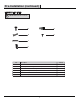
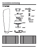
Pre-Installation (continued) HARDWARE INCLUDED NOTE: Hardware shown to actual size EE AA BB FF CC DD Part Description AA Blade screw BB 2 CC Mounting bracket screw (preassembled) Remote control holder mounting screws DD Light kit screw (preassembled) 6 EE FF Wire nuts Remote battery cover screw 8 Quantity 9+ 1 spare 2 1 4
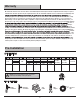
Pre-Installation (continued) PACKAGE CONTENTS M B E C N D F G O H J A Part A Description Blade K Quantity 3 Part H B Mounting bracket 1 J C Canopy Canopy cover 1 K L D E Description Fan motor assembly Light kit assembly 1 1 Light kit pan and shade assembly 1 1 Hanger ball (preassembled) 1 1 M 12V Battery Receiver F Downrod (preassembled) 1 N Remote control G Coupling cover 1 5 Quantity 1 1
Installation MOUNTING OPTIONS WARNING: To reduce the risk of fire, electric shock, or personal injury, mount the fan to an outlet box marked acceptable for fan support. An outlet box commonly used for the support of lighting fixtures may not be acceptable for fan support and may need to be replaced. If in doubt, consult a qualified electrician.
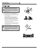
Assembly — Attaching the mounting bracket & Attaching the Fan Blade 1 2 Attaching the mounting bracket to the electrical box WARNING: To reduce the risk of fire, electric shock, or other personal injury, mount the fan only to an outlet box or supporting system marked acceptable for fan support and use the mounting screws provided with the outlet box. Attaching the downrod to the fan motor assembly □ Remove the nine blade screws (AA) from the fan motor assembly (H).
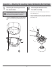
Assembly — Installing the Light Kit 3 4 Fastening the light kit and light kit assembly to the fan motor assembly □ Connect the light lead wire, attach the light kit assembly (J) to the fan motor assembly (H) by twisting left tightly. Fastening the Light kit pan and shade assembly to the fan motor assembly □ Remove six preassembled light kit pan screws (DD) □ Attach the light kit pan (K) to the fan motor assembly (H). Tighten light kit screws (BB) securely.
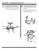
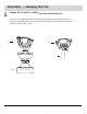
Assembly — Hanging the Fan 5 Hanging the fan motor assembly from the mounting bracket □ Lift the fan motor assembly (H) into position, and place the hanger ball (E) into the mounting bracket (B). Rotate the fan motor assembly (H) until the check groove drops into the registration slot and seats firmly. The downrod(F) should not rotate if this is done correctly.
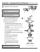
Assembly — Hanging the Fan (continued) 6 B Making the electrical connections WARNING: To avoid possible electrical shock, ensure the electricity is turned off at the circuit breaker or main fuse box before wiring. E M WARNING: Check to see that all connections are tight, including the ground, and that no bare wire is visible at the wire nuts, except for the ground wire. □ Insert the receiver (M) into the mouting bracket (B) with the flat side of the receiver (M) facing the ceiling.
Assembly — Hanging the Fan (continued) 7 Securing the fan motor assembly to the mounting bracket □ Remove two mounting bracket screws (BB) from the mounting bracket (B). □ Attach the canopy (D) to the mounting bracket (B) by using the two mounting bracket screws (BB) previously removed. □ Tighten the mounting bracket screws (BB) . □ Align the oval shape on the canopy (C) with canopy cover (D).
Operation REMOTE CONTROL OPERATING INSTRUCTIONS Install a 12V battery (L) into the remote control (N). Fasten the battery cover screw (FF) after installation. To prevent damage to the remote control, remove the battery if not used for long periods of time. WARNING: Do not short-circuit, disassemble, heat up, connect improperly, or dispose of used batteries in fire. Do not recharge or mix batteries with used or other battery types. Immediately remove used batteries. WARNING: Chemical Burn Hazard.
Operating your transmitter NOTE: On start up your ceiling fan will oscillate back and forth. This is NORMAL OPERATION for DC ceiling fan as it goes through its calibration cycle. The fan is NOT DEFECTIVE. □ Restore power to ceiling fan and test for proper operation. A. 1,2,3,4,5,6 buttons: These six buttons are used to set the fan speed as follows: 1 = low speed 2 = medium low speed 3 = medium speed 4 = medium high speed 5 = high speed 6 = Extra high speed B. button: This button turns the fan off.
Operation (continued) INSTALLING THE REMOTE CONTROL HOLDER □ Attach the remote control holder (M) with the two remote control holder mounting screws (CC). CC M Care and Cleaning Do Do not □ Check the support connections, brackets, and blade attachments twice a year. Ensure they are secure. Because of the fan’s natural movement, some connections may become loose over time. It is not necessary to remove the fan from the ceiling. □ Do not use water when cleaning.
Troubleshooting WARNING: Ensure the power is off at the electrical panel box before you attempt any repairs. Refer to the section “Making the Electrical Connections” on page 9. Problem Solution □ Check main and branch circuit fuses or breakers. The fan will not start. □ Check line wire connections to the fan and switch wire connections in the switch housing. □ Check to make sure the dip switches from the remote control and receiver are set to the same frequency.
FCC Statement This equipment has been tested and found to comply with the limits for a Class B digital device, pursuant to Part 15 of the FCC Rules. These limits are designed to provide reasonable protection against harmful interference in a residential installation. This equipment generates uses and can radiate radio frequency energy and, if not installed and used in accordance with the instructions, may cause harmful interference to radio communications.
BREEZISM