Making connections in a highspeed world 60GHz and 80GHz Wireless Ethernet Links NMS Manual i P/N 58000511 Revision F January 2008 58000511 rev.
60GHz and 80GHz Products NMS Manual Copyright Notice & Disclaimer Copyright © 20042008. BridgeWave Communications. All rights reserved. Printed in the USA No portion of this publication may be reproduced, copied, or distributed without the written consent of BridgeWave Communications. BridgeWave reserves the right to update or change the material in this publication at any time without notice.
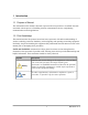
60GHz and 80GHz Products NMS Manual Table of Contents 1 Copyright Notice & Disclaimer ............. ii 7.1 User ......................................... 39 Export Control ...................................... ii 7.2 Administrator ........................... 39 Product Compatibility ........................... ii 7.3 Factory Access ......................... 40 7.4 Communities ............................ 41 7.5 Enhanced Security.................... 41 7.6 Logging Out.......................
1 Introduction 1.1 Purpose of Manual The information in this manual is directed to persons who must perform or coordinate the tasks associated with the process of installing wireless communication devices, and planning communication network applications. 1.2 Prior Knowledge This manual assumes the operator has at least basic experience with and an understanding of wireless technology and some familiarity with configuring and operating networking equipment.
0GHz and 80GHz Products NMS Manual 1.3 Contact Information Technical Assistance and Customer Service BridgeWave distributors and resellers are authorized local service providers and are responsible for immediate Tier 1 customer support. If problems are not resolved, contact BridgeWave Customer Service for assistance: Location: Santa Clara, CA USA Email: support@bridgewave.com Tech Support Hot Line: +1.408.567.6906 eService Center: http://bridgewave.
60GHz and 80GHz Products NMS Manual 2 System Overview This section provides an overview of the system design. A BridgeWave link consists of two radio terminals that transmit to each other on a full duplex channel pair, providing pointtopoint 100 Mbps or 1000 Mbps Ethernet connectivity between two locations. BridgeWave products are FDD (Frequency Division Duplex), transmitting on one frequency and receiving on a separate frequency at the same time.
60GHz and 80GHz Products NMS Manual Fiber 4 (ethFiber) Radio 5 (ethRadio) 1000BaseSX (Standard), or 1000BaseLX (Optional) fiber interface. Configurable for auto negotiation enabled or disabled. This interface is internally attached to the radio transmit and receive channel and provides the connection between the local and remote radio terminals. The interface operates in the following modes depending on product.
60GHz and 80GHz Products NMS Manual 3 Connecting to the NMS By default the units are configured for ‘InBand’ management and the web interface can be accessed through the copper, fiber, or over the link via the radio interface. The units are shipped with the factory default IP address set to 192.168.0.1 for LowBand units and 192.168.0.2 for HighBand units. Multiple users may concurrently access the radio management agent from different browser windows.
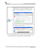
60GHz and 80GHz Products NMS Manual Depending on web browser version used, a certificate acceptance dialog window may be displayed when logging into an “AES” enabled product that requires https:// for establishing an SSL connection. Select the option that allows you to continue to the site. Some web browser versions will continue to highlight the address bar in red after choosing to continue. 5.
60GHz and 80GHz Products NMS Manual After logging on, the ‘Status’ screen will be displayed. The navigation bar across the top of the screen provides links to the following management functions: Status – Displays status indications and modes of operation for the units’ interfaces. Setup – Configure physical network interface settings and access options for the management agent. IP Setup – Configure DHCP or static IP addressing for the management interface.
60GHz and 80GHz Products NMS Manual 4 Installation Configuration The initial installation of the units involves configuring AdaptRate options (FE80U, FE60U and AR products only), fiber interface speed and duplex settings, selecting InBand or OutBand management options and setting IP addresses. The wireless link should be physically installed following the instructions found in the corresponding installation manual provided with the link.
60GHz and 80GHz Products NMS Manual Clicking the ‘AutoCal’ option causes the link to enter an out of service mode and is considered traffic affecting. The link will return to normal operating mode within 120 seconds. 3. Continue to click the ‘Maintenance’ tab to refresh the page. The calibration results will be displayed upon completion, and are automatically saved to flash.
60GHz and 80GHz Products NMS Manual 4.2 AR, GE, FE Rate Setup The ‘AdaptRate’ option is available on FE80U or FE60U (using GigE trial mode or upon AR upgrade) and AR products only. This feature allows for the link to operate in 1000 Mbps (GE) mode and temporarily switch to 100 Mbps (FE) mode to overcome fading conditions caused by severe rain events. This parameter can also be used to disable the AdaptRate feature and manually force the link to operate in FE or GE mode only.
60GHz and 80GHz Products NMS Manual 4. Select ‘Submit New Values’ at the bottom of the ‘Setup’ page. A red value will be displayed under the Current Effective Values column. Click the ‘Setup’ tab to refresh the browser window until the Current Effective Value is no longer displayed in red. 4.3 Fiber Interface All BridgeWave 60GHz and 80GHz radios are fitted with a Gigabit Ethernet fiber interface, regardless of whether the radio is operating in FE (100 Mbps) or GE (1000 Mbps) mode over the air.
60GHz and 80GHz Products NMS Manual 3. Select ‘Submit New Values’ at the bottom of the ‘Setup’ page. A red value will be displayed under the Current Effective Values column. Click the ‘Setup’ tab to refresh the browser window until the Current Effective Value is no longer displayed in red. 4.4 AdaptPath™ Secondary Path When an AdaptPath™ link reaches a predefined RSL level, the fiber traffic is directed to a secondary path attached to the copper interface such as a 5.4 or 5.
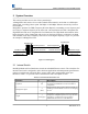
60GHz and 80GHz Products NMS Manual TX Fiber TX RX RX RX TX Fiber RX RX TX Copper TX TX RX Copper Secondary Radio Path Figure 41 AdaptPath™ Technology Use the following steps to configure the AdaptPath™ feature: After the equipment is installed, perform the following suggested steps to setup the LSP function in an AR system: 1. In the ‘Setup’ page on both Radios, set the Radio LSP to Fiber selection to ‘Enabled’ 2.
60GHz and 80GHz Products NMS Manual Setting RSL activation point values to zero: When the RSL Activation point is set to zero, the AdaptPath™ or LSP function will be continuously forced. When the RSL Deactivation point is set to zero, the function will not return after engagement. 4.
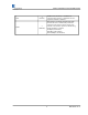
60GHz and 80GHz Products NMS Manual Switch Port Gets Notified That Link Is Down LowBand Radio TX Fiber TX RX RX RX TX Switch Port Gets Notified That Link Is Down HighBand Radio Fiber TX RX RX TX TX RX Copper (Management) Copper (Management) Core Network Redundant Path Figure 42 LSP LSP: Access to the web and SNMP management functionality will not be possible if the radio is being managed Inband through the fiber interface and LSP has disabled the fiber interface.
60GHz and 80GHz Products NMS Manual 3. Select Access control to either ‘InBand (Default) or OutBand (Copper Management Only) at both Radios 4. Press the ‘Submit New Values’ button at both radios. Testing the LSP function(s): 1. Put test apparatus or computers at each end of the link to ping or run traffic across the link 2. In the High band Radio’s ‘Maintenance’ page, set ‘Force LSP” and set the duration of the test to 199 minutes.
60GHz and 80GHz Products NMS Manual specify the configuration of the internal switch with respect to InBand or OutBand management. Detailed information about the InBand and OutBand options are provided in Section 4.6.1 and 4.6.2. 4.6.1 InBand (Default) This option allows for management of each radio terminal through the copper, fiber, and/or radio interface.
60GHz and 80GHz Products NMS Manual 4.6.2 Copper OutBand This option allows for management of each radio terminal through the copper interface, while keeping the management traffic isolated from the core network traffic. When the ‘Access Control’ parameter on the ‘Setup’ page is configured for OutBand (Copper Management Only), the internal switch isolates the copper interface from the fiber and radio interfaces by placing it into a separate port based VLAN.
60GHz and 80GHz Products NMS Manual Figure 45 OutBand Management Network Deployment Example 4.6.3 Configuring Management Access Use the following steps to configure the ‘Management Access’ option: 1. Connect to the web management interface of the unit and select the ‘Setup’ tab. 2. Under the ‘Access Control’ section select the desired ‘InBand (Default)’, or ‘OutBand (Copper Management Only)’ option.
60GHz and 80GHz Products NMS Manual 3. Click the ‘Submit New Values’ button at the bottom of the ‘Setup’ page for the changes to become active. 4.7 IP Setup The network addressing options are configured from the ‘IP Setup’ page of the web management interface. The network administrator would typically provide these values. Use the following steps to configure IP Setup parameters: 1. Connect to the web management interface of the unit and select the ‘IP Setup’ tab. 2.
60GHz and 80GHz Products NMS Manual After a restart it will take approximately 140 seconds for the web management interface to become accessible. The soft restart does not drop the radio link and data traffic will continue to flow. Advanced Security If secure management is desired for NonAES units, a license key to upgrade to HTTPS secure management can be purchased. Contact Sales for more information.
60GHz and 80GHz Products NMS Manual 5 Diagnostic Tools The status of a link can be determined by viewing the information contained on the ‘Status’ and ‘Statistics’ pages of the units web interface. The ‘Status’ page provides a variety of parameters that display Green, Yellow, or Red indications. A detailed description of the ‘Status’ page parameters are listed in Section 5.1. The ‘Statistics’ page provides transmit and receive statistics counters for the Copper, Fiber, and Radio interfaces. Section 5.
60GHz and 80GHz Products NMS Manual Figure 51 Status Page USER: Indicates the currently loggedin username STATUS Model: Indicates the type of unit. HighBand or Low Band: Indicates the frequency band of the radio’s transmitter. A link consists of one lowband and one highband radio. MAC: Displays the MAC address of the management NMS interface. UNIT Up time: Time since last unit power cycle, soft restart, or hard restart. 23 58000511 rev.
60GHz and 80GHz Products NMS Manual Calibration Results: This parameter displays the results of the calibration performed during installation or via the ‘AutoCalibration’ option performed from the maintenance page. Prior to viewing the calibration results a ‘Get Results’ should be performed from the Maintenance screen of the web interface. This ensures that the displayed results are synchronized with the active values stored in the flash of the MCU.
60GHz and 80GHz Products NMS Manual YELLOW: This indicates that errors in the transmission are occurring. The system contains built in Forward Error Correction (FEC) that will correct most errors that occur near the receive signal threshold. If ‘Corrected Errors’ is displayed then the FEC is correcting all errors and the user traffic is unaffected. If ‘Uncorrected Errors’ is displayed the FEC is no longer able to correct all errors and some user data packets could be dropped.
60GHz and 80GHz Products NMS Manual Transmitter Temp: Internal temperature of the radio transmitter GREEN: Within specification (20oC to 75oC) (4oF to 167oF) YELLOW: At operating limit Min/Max transmitter temperature is also displayed from the last restart of the unit. Packets Received: Number of packets received by the radio interface since last refresh of the management interface from any active user session.
60GHz and 80GHz Products NMS Manual COPPER Link Status: Displays the physical status and copper backup active message for the 10/100BaseT copper interface. GREEN: Port is up RED: Port is down (Normal if copper port is not used) The Copper interface is set for Auto Negotiation only. The negotiated speed and duplex are displayed Packets Received: Number of packets received by the copper interface since last refresh of the management interface from any active user session.
60GHz and 80GHz Products NMS Manual An example of the ‘Statistics’ page is shown in Figure 52 and a definition of each parameter follows. Figure 52 Statistics Page 28 58000511 rev.
60GHz and 80GHz Products NMS Manual 5.2.1 Receive and Transmit Good Octets: An octet is a sequence of eight bits. Since a byte is not eight bits in all computer systems, octet provides an unambiguous term. . When a packet is in error, none of the octets are counted as “good”. Total good packets: Total number of packets without errors received. For the transmit direction this is expressed as total packets sent, since only good packets are sent.
60GHz and 80GHz Products NMS Manual CRC errors: Short for Cyclic Redundancy Check, CRC is a method of detecting errors in data transmission. A CRC is control information sent with a block of data that when received can be used to verify that all data was received correctly. CRC errors typically indicate physical defects in fiber or copper cabling, or poor receive signal quality on a radio link.
60GHz and 80GHz Products NMS Manual 5.3 AES Statistics In AES systems transmitting encrypted data, the statistics screen will appear slightly different as shown in Figure 53, Statistics screen for AES encrypted traffic, indicating that the Radio traffic is encrypted Figure 53, Statistics screen for AES encrypted traffic 31 58000511 rev.
60GHz and 80GHz Products NMS Manual 5.4 TX Mute Function The Transmitter (TX) mute function can be useful for investigating and diagnosing interference related problems. Use the following steps to mute the Transmitter 1. Connect to the web management interface of the unit and select the ‘Maintenance’ tab. 2. Under the Transmitter section, select TX Mute. 3. Select the amount of time required for the TX Mute operation. The range is 199 minutes.
60GHz and 80GHz Products NMS Manual 6 SNMP Simple Network Management Protocol (SNMP) is a standardized protocol used for monitoring and controlling various elements within a network. All BridgeWave products that are network management enabled provide SNMP V2 support for GET and SET commands on MIB2 and BridgeWave enterprise MIB objects. Traps are sent in SNMP V1 format. SNMP V1 and V2 MIBS are included in .zip file for each software release. The .
60GHz and 80GHz Products NMS Manual System Contact: Identification of the contact person for this managed node, together with information on how to contact this person. 3. Next, enter the ‘IP address’, ‘Host Name’, and trap ‘Community’ of the management station(s) that will be monitoring this unit. All SNMP alarms (traps) will be sent to the host specified in this section. A maximum of three trap destinations can be configured.
60GHz and 80GHz Products NMS Manual 6.2 SNMP MIB Information BridgeWave supplies an enterprise MIB file that provides definitions of objects beyond the standard MIB2 objects. This MIB file can be found on the CD that is included with the product and on BridgeWave’s website: http://www.bridgewave.com/support/downloads.cfm. To install the BridgeWave MIB file on your network management station, follow the instructions provided with your network management station software.
60GHz and 80GHz Products NMS Manual BridgeWave Enterprise MIB Objects Table 6.22 BridgeWave Enterprise MIB Objects Name OID Description brwaveUnitSn 1.3.6.1.4.1.6080.2.1 brwaveCommon 1 1.3.6.1.4.1.6080.2.2 brwaveCommon 2 1.3.6.1.4.1.6080.2.6 brwaveCommon 6 1.3.6.1.4.1.6080.3.1.2.1 brwaveFactorySetup 1 1.3.6.1.4.1.6080.3.1.2.3 brwaveFactorySetup 3 1.3.6.1.4.1.6080.3.1.3.1 brwaveRadioStatus 1 1.3.6.1.4.1.6080.3.1.3.2 brwaveRadioStatus 2 1.3.6.1.4.1.6080.3.1.3.3 brwaveRadioStatus 3 1.3.6.1.4.1.6080.3.1.
60GHz and 80GHz Products NMS Manual BridgeWave Enterprise MIB Traps Table 6.23 Bridgewave Enterprise MIB Traps Name brwaveErrorsOverThreshold OID 1.3.6.1.4.1.6080.3.1.9.0.1 brwaveRadioEventsV2 1 brwaveErrorsUnderThreshold 1.3.6.1.4.1.6080.3.1.9.0.2 brwaveRadioEventsV2 2 brwaveUnitTemperatureAbnormal 1.3.6.1.4.1.6080.3.1.9.0.3 brwaveRadioEventsV2 3 brwaveUnitTemperatureNormal 1.3.6.1.4.1.6080.3.1.9.0.4 brwaveRadioEventsV2 4 1.3.6.1.4.1.6080.3.1.9.0.
60GHz and 80GHz Products NMS Manual 7 User Accounts & Passwords The management agent supports two types of users, with varying capabilities. The Administrator (username=’admin’) may view status and statistics, view/modify unit configuration, and perform maintenance functions (including software update). The User (username=’user’) may view status, configuration, and statistics, but is prevented from modifying unit configuration or performing maintenance functions.
60GHz and 80GHz Products NMS Manual 7.1 User Permits read only capability such as viewing of unit status, configuration parameters and statistics. Does not permit modification of any parameter, setting passwords or performing maintenance functions. A history of the last 15 passwords is maintained to prevent password reuse. The user password can be set or reset by the administrator.
60GHz and 80GHz Products NMS Manual If a value other than 0 has been set in the ‘Password Expires’ field of the ‘Enhanced Security’ section this field will display the amount of time remaining until the password expires. If the password has expired, it will show how long since expiration and will be displayed in red. Once the password has expired, the ‘admin’ user will be forced to change the value of the password at the next login, before any other operations will be permitted.
60GHz and 80GHz Products NMS Manual 7.4 Communities Read and write community strings are used for permitting SNMP management access. The Community strings are casesensitive and can have 012 characters comprised of numbers, letters, or special characters. Read Only: Used for authentication of SNMP GET request. Default value is ‘public’. Read/Write: Used for authentication of SNMP SET request. Default value is ‘private’.
60GHz and 80GHz Products NMS Manual Permits the extension of the time between automatic session timeouts to a value of 199 minutes. 7.6 Logging Out User connections to the web management agent will automatically log out after 5 minutes (default) of inactivity unless reconfigured in the ‘Enhanced Security’ function. The ‘Log Out’ option can be used to manually close the User’s connection to the management agent.
60GHz and 80GHz Products NMS Manual 8 RADIUS Remote Authentication Dial In User Service (RADIUS) standard (RFC 2865) allows for remote and centralized user administration, authentication and authorization of the BridgeWave Radio user names and passwords when the radios are embedded in a network environment. When RADIUS is enabled in the BridgeWave radio and a user attempts to login to the radio, the radio will send the authentication request to the specified RADIUS server.
60GHz and 80GHz Products NMS Manual Figure 81: RADIUS Setup Page One possible safe approach to take is to first enable RADIUS and allow local user login access. Now open a new browser window and login with a username and password provided by the RADIUS server. When the login through the RADIUS server is successful, it is safe to reenable RADIUS in the radio, disallowing local user access. 44 58000511 rev.
60GHz and 80GHz Products NMS Manual 9 Configuration File Management A copy of the unit’s configuration can be saved to an external file. The file is saved in an .ini format and can be viewed with a text editor. 9.1 Backing Up a Configuration Use the following steps to perform a backup of the unit configuration. 1. Select the ‘Maintenance’ tab from the web browser interface of the unit. 2. Select the ‘Backup‘ option from the ‘Config’ section of the ‘Maintenance’ screen. 3.
60GHz and 80GHz Products NMS Manual Care should be taken during the editing process to not disturb any other characters other than what is typed between the quotation marks Care should also be taken when saving the file to keep the .ini extension intact. This is done by selecting “all files as the save type and making sure that the filename has .ini at the end of the filename. 9.3 Restoring a Configuration Use the following steps to restore the unit configuration from a backup .ini file. 1.
60GHz and 80GHz Products NMS Manual 10 Upgrading Software 10.1 Determining Versions The ‘Versions’ section on the ‘Maintenance’ page of the web interface, shown in Figure 101, displays a detailed inventory of a unit’s hardware and software components. The information may be needed when contacting factory personnel to help resolve issues or when updating a unit’s software.
60GHz and 80GHz Products NMS Manual 10.2 Software Upgrade Procedure To obtain the latest version of software, go to the download section of the BridgeWave website at http://www.bridgewave.com/support/downloads.cfm. You will find a list of software updates available for your product. The download consists of a dated .zip file that includes the product software, MIB files and the release notes for the package. Use the following steps to upgrade a unit’s software: 1.
60GHz and 80GHz Products NMS Manual Figure 102 File Upload Success Page If no indication or a failure message is received after ten minutes, please verify the file name and retry the upload. If the failure repeats, please reupload the file from the BridgeWave website and retry. If the failure still repeats, please contact customer service. 6. After receiving a ‘File Upload Success’ perform a ‘Soft Restart’ from the ‘Maintenance’ page of the web interface.
60GHz and 80GHz Products NMS Manual When upgrading the MCU_AESxxxxxx.cat file of a remote radio over the wireless interface, the link traffic may drop while the file is being burned to flash. This can cause the ‘File Upload Success’ message to not be received by the upgrade PC at the local end. If a success message is not received after waiting 15 minutes reconnect to the remote radios web interface and verify the new MCU version is displayed before proceeding with the remaining steps. 8.
60GHz and 80GHz Products NMS Manual 11 System Restarts The following types of restarts can be performed on the unit from the ‘Maintenance’ page of the web management interface: Soft Restart – Performs a soft restart of the unit. This will activate the latest changes submitted from the Setup page. If no changes have been made it will maintain the current configuration settings. A restart will not stop data transfer, but will make the management agent inaccessible for approximately 140 seconds.
60GHz and 80GHz Products NMS Manual 12 FEU, AR Trial Mode The FE80U product is a 100 Mbps Fast Ethernet link that is software upgradeable in the field to Adaptive Rate (AR). The AR feature allows the link to operate in Gigabit Ethernet (1000 Mbps) mode and automatically switch down into Fast Ethernet (100 Mbps) mode during fading conditions caused by rain. A FE80U comes with an AR demo mode that allows it to be operated as an AR for a period of 30 days once the demo mode is enabled.
60GHz and 80GHz Products NMS Manual Figure 121 FEU Upgrade File 4. This file must then be emailed to BridgeWave after purchasing an upgrade. 5. Once the upgrade has been purchased, BridgeWave will email a license file that must be uploaded to the HighBand unit. Save this file to a known location. The unit’s software should not be upgraded until after the license file has been received and properly installed. 6. From the web interface of the HighBand unit select the ‘Maintenance’ tab.
60GHz and 80GHz Products NMS Manual 13 AES Encryption Feature The Advanced Encryption Standard (AES) feature provides a method for securing the data traffic traveling across the radio link by encrypting the information. The AES feature and the associated procedures in this section only apply to BridgeWave products that include the “AES” designator in the model number. Example: AR80XAES In cryptography, AES is a block cipher adopted as an encryption standard by the U.S. government.
60GHz and 80GHz Products NMS Manual 13.1 AES Setup Use the following procedure to configure and enable AES encryption: AES setup requires secure management to be enabled. This can be verified in the ‘IP Setup’ page as shown: 1. AES should only be configured after proper installation has been completed and an unencrypted link has been established and validated. Confirm you are working with a fully operational link. 2.
GHz and 80GHz Products NMS Manual Click on the ‘AES’ tab to refresh the page until the buttons are no longer grayed out. Do not hit the browser ‘Refresh’ option to update the page. This will cause the key to resave and the buttons will continue to be grayed out. Please be patient. It may take up to 4 minutes for the 256 key data to be written to the radio memory. The buttons on the AES page will be grayed out during this process. 4.
60GHz and 80GHz Products NMS Manual If connectivity across the link cannot be established after enabling encryption, check the ‘Packets Received’ field under the ‘Radio Interface’ section of the ‘Status’ tab. If errors are displayed followed by the ‘Check AES setup’ message, shown below, the keys are most likely mismatched and should be reentered into both local and remote units. 57 58000511 rev.
60GHz and 80GHz Products NMS Manual 14 SysLog SysLog is a communications protocol as well as program applications used for forwarding, storing and processing log messages in a heterogeneous IP network SysLog is based on standards RFC 3164 and RFC 3195 The Syslog protocol is a clientserver type protocol. The Syslog sender, in this case, the BridgeWave radio, may be enabled to send small textual messages to the Syslog server program.
60GHz and 80GHz Products NMS Manual 14.2 Local Syslog Message Display As shown in Figure 141, Local Syslog Message display, ‘Up Time, ‘Severity’, ‘Source’ and ‘Message’ information is presented for the operator. The ‘Save Into File” button transfers the SysLog data to an Excel file Figure 141, Local Syslog Message display 14.3 Syslog Setup The Syslog server destination is setup on the SNMP page as follows: 1. Select the SNMP tab from the web browser interface of the unit 2.
60GHz and 80GHz Products NMS Manual 15 Default Recovery (Hard Reset) If the unit’s Administrator password or IP configuration is forgotten, it will be necessary to perform a hard reset to return these parameters to the factory default values. Only the Administrator/User/Factory passwords, IP configuration, and Management Access parameters will be reset to default values. All other parameters will remain in their currently configured state.
60GHz and 80GHz Products NMS Manual Making your own hard reset cable: If you do not have access to the hard reset box supplied with the unit, you can create your own “hard reset cable” using the following procedure: 1. Obtain a standard Ethernet patch cable at least 3m in length. 2. Cut off one end of the Ethernet patch cable and then strip the jacket from the two wires that belong to pins 3 and 6.
60GHz and 80GHz Products NMS Manual (End of NMS manual, this page intentionally left blank) 62 58000511 rev.