
Communications, Inc. Switch User Manual


TM
GE/AR80 Installation Manual
580-00519, rev A 9 of 40
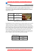
2.4 Link Distance
Measurement of the link distance is important in estimating the link availability and
calculating expected Receive Signal Level (RSL). This measurement can be performed
using the Latitude and Longitude coordinate readings from a Global Positioning System
(GPS) device, which is placed near the proposed locations of the antennas. Additionally
GPS reading will be required in order to comply with the FCC registration process.
To quickly obtain estimated distances and availabilities for a given product and region,
use BridgeWave’s path calculator. To obtain the latest version of BridgeWave’s Path
calculator, contact BridgeWave’s Customer Service.
2.5 Antenna Location
The optimum location for the antennas must be determined. The ideal location should
pr
ovide for ease of erecting and mounting the antenna, as well as providing unimpeded
LOS to the remote location. The following factors should be taken into account:
• Type of mounting—fixed or roof-safe pole mounting
• Location where the fiber and DC power wiring will enter/exit the building
• Length of cable runs
• Grounding connection points
• Obstructions, including allowances for tree growth
• Accessibility of mounting location
• Access to building after regular working hours
2.6 Cabling
The installation site should be inspected to determine the run paths for the fiber cable and
po
wer cable from the radio equipment to the termination point. Locations for roof
penetration should be identified. The routing and securing of all cables should conform to
all applicable codes and requirements. Depending on the likelihood of damage due to foot
traffic or equipment movement, cabling conduit may be required. The maximum cable
run length as specified for the equipment being installed must not be exceeded.
* For pricing and a quotation, visit MeridianMicrowave.com
* For pricing and a quotation, visit MeridianMicrowave.com