
Manual


FeaturesandControls
Read this Operator'sManual and safetyrules before operating yourgenerator.
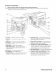
Comparethe illustrations with your generator, to familiarize yourself with the locations of various controls and
adjustments. Save this manual for future reference.
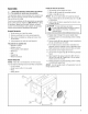
A - FuelTank -- Capacityof seven (7) U.S. gallons.
B - Fuel Valve-- Usedto turn fuel supply on and off to
engine.
C- ChokeLever-- Usedwhen starting a cold engine.
D - Air Cleaner-- Protects engine by filtering dust and
debris out of intake air.
E - Recoil Starter -- Usedto start the engine.
F - EngineRocker Switch -- Set this switch to ONor I
before using recoil starter. Set switch to OFFor 0 to
switch off engine.
G - 0it Fiii Cap-- Checkand add engineoil here.
H - 0il DrainPlug -- Drainengine oil here.
J - GroundingFastener -- Consult your local agencyhaving
jurisdiction for grounding requirements in your area.
K - Identification Label-- Provides model, revision and
serial number of generator. Pleasehavethese readily
available when calling for assistance.
L =Rocker Switch Circuit Breaker-- The receptaclesare
provided with a rocker switch circuit breaker to protect
the generator against electrical overload.
IVl- 120/240 Volt AC, 30 Amp LockingReceptacle -- May
be used to supply electrical power for the operation of
120 and/or 240 Volt AC, 30 Amp, single phase,60 Hz
electrical, lighting, appliance, tool and motor loads.
N - Spark Arrestor Muffler -- Exhaustmuffler lowers engine
noise and is equipped with a spark arrester screen.
P - 120 Volt AC, 20 Amp, Duplex Receptacles -- May be
used to supply electrical power for the operation of
120 Volt AC, 20 Amp, single phase, 60 Hzelectrical,
lighting, appliance,tool and motor loads.
10 BRIGGSandSTRATTON.COIVl