
Manual


Assembly
F[-_-_I Read entire operator's manualbefore you attempt
to assemble or operate yournew generator.
Your generator requires some assembly and is ready for use
after it has been properly servicedwith the recommended
fuel and oil level is verified.
If you haveany problemswith the assemblyof your generator,
pleasecall the generator helplineat (800) 743-4115. If calling
for assistance,pleasehavethe model, revision, and serial
number from the identificationlabel available.Seegenerator
Featuresand Controlsfor identification labellocation.
UnpackGenerator
1. Set the carton on a rigid, fiat surface.
2. Remove everything from carton except generator.
3. Opencarton completely by cutting each corner from
top to bottom.
4. Leave generator on carton to install wheel kit.
The generator is suppliedwith:
* Operator's manual
* Adapter cord set
* Three packets of fuel stabilizer
* Wheels (2)
* Axle
* Support leg
* Wheel kit hardware
Install Wheel Kit
NOTICE Wheel kit is not intended for over-the-road use.
You will needthe following tools to install thesecomponents:
* 13 mm wrench
* Socket wrench with a 13 mm socket
* Pliers
* Safety glasses
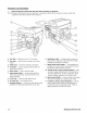
Install the wheel kit as follows:
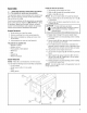
1. Tip generator so that engine end is up.
2. Slide axle (A) through both mounting brackets.
3. Slide a wheel (B) over axle.
NOtiCE Besure to install wheel with raised hub inboard.
4. Place a washer (C) on axle and then placean e-ring (D)
in axle groove.
5. Install e-ring with pliers, squeezingfrom top of e-ring
to bottom of axle.
,_, CAUTION E-rings could causeeye injury.
E-rings could spring backand becomeairborne
when installing or removing, resulting in
moderate injury.
* Alwaysweareyeprotectionwheninstalling/removinge-rings.
6. Repeatsteps 3 through 5 to secure secondwheel.
7. Return generator to normal operating position (resting
on wheels).
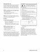
8. Remove handle (H) from generator frame by pushing in
pins (J) and pulling up on handle.
9. Turn handle around as shown below and attach it to
generator frame by pushing in pins on generator frame.
Slide handle down until pins lock into holes on handle.
10. Tip generator so that engine side is down.
11. Line up holes in support leg (E) with holes in generator
frame.
12. Attach support leg using 2 capscrews (M8 x 20 mm)
(F) and 2 hex nuts (G). Tighten with a 13 mm socket
wrench and 13 mm wrench.
13. Return generator to normal operating position (resting
on wheels and support leg).
NOTICE Turn the handle around on the generatorframe for
storage purposes ONLY.
?