
Use and Care Manual

Models 744LED / 744LEDNT Recessed Fan / Light
READ AND SAVE THESE INSTRUCTIONS
WARNING
TO REDUCE THE RISK OF FIRE, ELECTRIC SHOCK, OR INJURY TO
PERSONS, OBSERVE THE FOLLOWING:
1. Use this unit only in the manner intended by the manufacturer. If
you have questions, contact the manufacturer at the address or
telephone number listed in the warranty.
2. Before servicing or cleaning unit, switch power off at service panel
and lock the service disconnecting means to prevent power from
being switched on accidentally. When the service disconnecting
means cannot be locked, securely fasten a prominent warning
device, such as a tag, to the service panel.
3. Installation work and electrical wiring must be done by a qualified
person(s) in accordance with all applicable codes and standards,
including fire-rated construction codes and standards.
4. Sufficient air is needed for proper combustion and exhausting of
gases through the flue (chimney) of fuel burning equipment to pre-
vent backdrafting. Follow the heating equipment manufacturer’s
guideline and safety standards such as those published by the
National Fire Protection Association (NFPA), and the American
Society for Heating, Refrigeration and Air Conditioning Engineers
(ASHRAE), and the local code authorities.
5. When cutting or drilling into wall or ceiling, do not damage elec-
trical wiring and other hidden utilities.
6. Ducted fans must always be vented to the outdoors.
7. If this unit is to be installed over a tub or shower, it must be
marked as appropriate for the application and be connected to a
GFCI (Ground Fault Interrupter) - protected branch circuit.
8. Never place a switch where it can be reached from a tub or shower.
9. Install this unit in a flat ceiling only.
10. For use in non fire rated installations only.
11. Not for use in environmental air handling spaces.
12. CAUTION - RISK OF FIRE AND PERSONAL INJURY: 75W
MA X . L A MP. Use R30, BR30, PAR30L, or PAR30LN lamps only
(75W Max.). For wet locations (tub or shower) - use PAR30L or
PAR30LN (75W Max.) lamp only. Use no other lamp types. Do
not install a lamp indentified for use only in enclosed luminaries.
13. Do not install in a ceiling thermally insulated to a value greater
than R60.
14. This unit must be grounded.
CAUTION
!
1. For general ventilating use only. Do not use to exhaust hazardous
or explosive materials and vapors.
2. To avoid motor bearing damage and noisy and/or unbalanced
impellers, use the cardboard protector (provided) to keep drywall
spray, construction dust, etc. off power unit.
3.
The LED bulb used with this product twists into the bulb socket.
Do not attempt to insert or remove bulb by pushing it straight
in or pulling it straight down.
4. Please read specification label on product for further information
and requirements.
To clean trim ring / bafe: Vacuum with a soft brush attachment or
remove trim ring / baffle and clean with a soft cloth and mild soap
or detergent. Dry thoroughly before reinstalling.
To clean inside of housing: Remove trim ring / baffle and vacuum
inside of housing with a soft brush attachment.
OPERATION
The fan and light can be operated using various combinations of
on/off switches and controls:
• Fan and light controlled with single on/off switch
• Fan and light controlled with separate on/off switches
• Fan controlled with timer control
• Fan controlled with speed control
See “Connect Wiring” section for various wiring options.
CLEANING
MAINTENANCE
Motor is permanently lubricated. Do not oil or disassemble motor.
See “Service Parts” section for a list and illustrations of service parts.
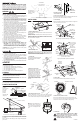
Two of the most common ways to connect ductwork to the unit.
PLAN THE INSTALLATION
The unit can
be installed
anywhere
between ceiling
joists using
mounting
brackets
provided.
*
Install in a flat
ceiling only.
Typical Installation
The unit will operate most quietly and efficiently when located where
the shortest possible duct run and minimum number of elbows will
be needed.
Plan to supply the unit with proper line voltage and appropriate
power cable.
ROOF CAP
**
4-IN. ROUND
ELBOW
**
4-IN. ROUND
DUCT **
WALL
CAP
**
** Purchase separately
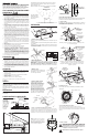
INSTALLATION
2. Mark mounting location.
Position unit between joists and extend mounting brackets.
IMPORTANT: Position brackets so there will be an 1/8” gap
between bottom of housing and ceiling material. Mark the top of
keyhole slot on all four mounting brackets.
COOKING AREA
Do not install above
or inside this area
Cooking
Equipment
Floor
45
45
The unit must not
be installed above or
inside the cooking
area shown.
Do not install in a cooking area.
HOUSING
MOUNTING
BRACKET
CEILING
JOIST
POWER
CABLE
TRIM RING / BAFFLE
FINISHED CEILING
4" ROUND
DAMPER/DUCT
CONNECTOR
*
1/8" GAP
1. Install mounting brackets.
Slide the adjustable mounting brackets into the bracket channels
on the housing.
Bend the tabs on the cardboard protector and insert protector into
opening in housing.
NOTE: The cardboard protector shields the inside of the housing
from drywall spray and construction dust. Do not remove it until
after construction is completed.
CARDBOARD PROTECTOR
Register this product at www.broan.com/register. For Warranty
Statement, or to order Service Parts: go to www.broan.com or www.
nutone.com and type the Model in the “Model Search” field at the top of
the page. Broan, 926 W. State Street, Hartford, WI 53027 800-637-1453
3. Pound in nails.
Remove unit temporarily, and pound
nails partially into joists at all four
marked locations.
4. Hang and secure housing.
Hang unit from nails. Check to make
sure that there will be a 1/8” gap
between bottom of housing and
ceiling material. Pound nails tight.
For wide joist centers: A #8 x 3/8
self-tapping screw can be used to
join extended brackets together and
create a rigid mount. To ensure a
noise-free mount, crimp the bracket
channels tightly around mounting
brackets.
5. Attach damper/duct connector.
Snap the damper/duct connector onto housing. Make sure that
tabs on the connector lock in housing slots. (Top of damper/duct
connector will be flush with top of housing.) Install ductwork.
FLUSH
NOTE: Make sure damper flap is in
place inside of duct connector. If it
is not: Squeeze top and bottom of
connector to snap flap back into
place.
7. Connect wiring.
Unit can be wired from outside of housing as shown. Use UL approved
connectors to wire per local codes.
6. Choose power cable direction.
Remove wiring plate. When re-attached, the wiring plate allows the
power cable to enter unit horizontally or vertically.
HORIZONTAL POWER
CABLE CONNECTION
VERTICAL
POWER CABLE
CONNECTION
1102398A
FINISHED
CEILING
MATERIAL
HOUSING
COLLAR
CLEARANCE
HOLE
8. Finish ceiling.
Cut an opening in finished ceiling material for housing collar.
WIRING PLATE
WHITE
TO
WHITE
BLUE (FAN)
TO
BLACK
TOP / BACK
OF HOUSING
3-WIRE PLUS
GROUND
POWER
CABLE
GROUND TO
WIRING PLATE
Fan operated with separate on/off switch,
speed control or timer.
Light operated with separate on/off switch.
Fan and Light operated with single on/off switch
BLACK (LAMP)
TO RED
WIRING PLATE
WHITE
TO
WHITE
BLUE AND
BLACK
TO BLACK
TOP / BACK
OF HOUSING
2-WIRE PLUS
GROUND
POWER
CABLE
GROUND TO
WIRING PLATE
9. Attach trim ring / bafe to housing.
Remove the cardboard protector from inside the housing collar.
Use a pencil to insert one end of each spring into the holes on the
lamp bracket. Center trim ring / baffle in ceiling opening.
10. Install bulb.
SPRINGS
TRIM RING / BAFFLE
LAMP
BRACKET
CAUTION: Twist bulb to install or remove.
CAUTION - RISK OF FIRE: Use only R30, BR30, or PAR30
shaped, 10W LED bulb with GU24 base (supplied).
Replacement bulbs can be ordered from Broan if not
available locally (see service parts list).
!