
Installation Manual

2
PREPARACION
PASOS DEL 1 AL 3 -
SOLO PARA MODELOS 655, 659, Y 659F
1. Asegúrese de que el conjunto del calentador está
desconectado del enchufe ROJO.
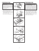
2. Afloje los dos tornillo de retén en el interior de la
abertura de descarga del calentador. Coloque la punta
del destornillador entre la pared exterior de la abertura
de descarga y la caja del ventilador. Haga palanca
suavemente hacia afuera hasta que la abertura del escape
se deslice del borde de apoyo en la caja exterior. (FIG. 1)
3. Desenganche los pasadores de la bisagra y levante el
conjunto del calentador hacia afuera de la caja. (FIG. 2)
4. Desconecte el conjunto del ventilador del enchufe
NEGRO. Saque la bolsa de plástico y déjela a un lado.
5. Saque el tornillo de montaje y levante con cuidado el
conjunto del ventilador hacia afuera de la caja. (FIG. 3)
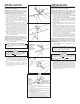
6. Refiérase al diagrama de conexiones de la unidad
en la página siguiente. Saque los discos removibles
apropiados introduciendo la punta del destornillador
en las ranuras y moviendo éste de un lado a otro hasta
romper las lengüetas. (FIG. 4)
7. Meta los soportes de montaje ajustables en los canales
para los soportes en la caja. (FIG. 5)
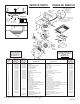
PREPARATION
STEPS 1 THRU 3 - MODELS 655, 659 & 659F ONLY
1. Make sure the heater assembly is unplugged from
the RED receptacle.
2. Loosen the two retaining screws on the inside of
the heater discharge opening. Place a screwdriver
tip between the outer wall of the discharge open-
ing and the fan housing. Gently pry outward until
the exhaust discharge slips off the support lip on
the outer housing. (FIG. 1)
3. Unhook hinge pins and lift heater assembly out
of housing. (FIG. 2)
4. Unplug the fan assembly from the BLACK receptacle.
Remove the plastic bag and set it aside.
5. Remove the mounting screw and carefully lift the fan
assembly out of the housing. (FIG. 3)
6. Refer to the wiring diagram of your unit on the next
page. Remove appropriate knockout(s) by inserting
a screwdriver blade into slots and bending it back
and forth to break tabs. (FIG. 4)
7. Insert the adjustable mounting brackets into the
bracket channels on the housing. (FIG. 5)
FIG. 1
FIG. 2
FIG. 3
FIG. 4
FIG. 5
KNOCKOUTS
DISCOS
REMOVIBLES
RETAINING
SCREWS
TORNILLOS
DE RETEN
HINGE PIN
PASADORE DE
LA BISAGRA