
ADA Compliant Statement


2
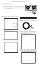
THIS PROCEDURE APPLIES TO THE FOLLOWING RANGE
HOOD SERIES
Broan Series: BCDF, BKDB, BCDA, BKDD, BKDEG, BKDF, CLDA,
CRDEG, BNDD, BNDF and BQDD.
NuTone Series: AHDA, AVDF, NKDF, NQDD and NCDA.
Venmar Chef Series: VCNDD and VCQDD.
Venmar Bistro Series: VBLDF.
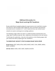
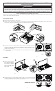
K Close the control access panel and reinstall the blower by reversing
steps G to D on first page. Run the ADA cable section through the
provided ferrite, making 2 loops. The ferrite must be as close as possible
to the access panel.
HD0953
L Open the provided connection box. Using long nose pliers, break away
2 cable entry notches on the lid (one per side).
HR0156
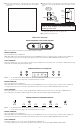
M Peel off the paper backing on back of connection box base and install
the base at the location shown. Make sure that the surface is clean. This
will place the connection box within the Wire Cover area near the blower
connector. IMPORTANT NOTE: The base must be positioned flush to the
notches (see circled area below).
HD0954
HE0278
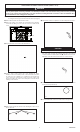
O Using small UL approved wire nuts (suitable for 22 AWG wires), connect
wires as follow: WHITE wire with WHITE wire, BLACK wire with BLACK
wire and RED wire with RED wire.
HD0955
P Put the wire nuts inside the connection box base, then snap the
connection box lid on its base, ensuring the ADA cable runs through
the open notches.
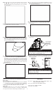
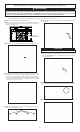
R Install a momentary contact switch at a convenient place for the user.
Connect the end without connector of the provided ADA cable to this
switch as shown below:
HE0277
N Use the remaining cable length of 15 ft. (from step H) to connect to the
remote ADA switch outside the hood (step R). IMPORTANT: Leave a
cable length of at least 12” that protrudes from the wall (at the same
location of the 120 V house wiring). Run one end of the remaining
section of the ADA cable though the range hood wire clamp, along with
the power cable, giving enough length to make the connections inside
the box. Tighten the wire clamp, then strip the end of the 3 wires from
both ADA cable ends.
NOTE: The wire clamp must be suitable for 2 cables.
Q Reinstall the hood wiring cover and attach it to the hood using its
retaining screw.
HD0741
SCREW
TABS ON INNER
TOP OF HOOD
ENGAGED IN
WIRING COVER
SLOTS.
CAUTION
Ensure both tabs on inner top of hood are engaged in their
corresponding slots in wiring cover. Also, take care not to
pinch wires while reinstalling wiring cover.
HE0279A
COMMON
MOMENTARY
NORMALLY OPEN
CONTACT SWITCH
(back view)
WHITE
ADA CABLE
TO HOOD
RED
(motor)
BLACK
(lights)
Motor
control
Light
control
CAUTION
Use one SPDT normally open, momentary contact switch
(shown in above diagram) or two SPST normally open,
momentary contact switch.
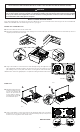
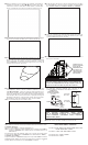
S Put back in place the hood filters and restore power to the range hood.
NOTE: Use the control on the range hood to reset the filter maintenance indicator.
Motor control
Press to turn ON the blower on LOW speed.
NOTE: When LOW speed is activated from OFF, the blower starts on MEDIUM
speed for a very short lapse of time, and then resumes to LOW speed.
To change the blower speed, press on this button again until the desired
speed is reached (from LOW to MEDIUM to HIGH speed to OFF).
Light control
When lights are OFF, press once on this control to turn ON the lights
on LOW intensity. Press another time to set the lights on HIGH intensity.
Pressing another time after the HIGH setting will turn OFF the lights.
RANGE HOOD OPERATION