INSTALLATION INSTRUCTIONS ® ODEL Z_INTENDED FOR DOMESTIC COOKING ONLY_ iNSTALLER: LEAVE THiS MANUAL WiTH HOMEOWNER. HOMEOWNER: USE AND CARE INFORMATION ON PAGES 12 AND 13. Broan=NuTone LLC; Hartford, Wisconsin www.broan.com 1-800-558-1711 REGISTER YOUR PRODUCT ONLINE AT: www.broan.com/register SV09440 rev.
WARNING WARNING TO REDUCE THE RiSK OF FIRE, ELECTRIC SHOCK OR iNJURY TO PERSONS, OBSERVE THE FOLLOWING: TO REDUCETHE IN THE EVENT FIRE, OBSERVE 1. Use this unit only in the manner intended by the manufacturer, if you have questions, contact the manufacturer at the address or telephone number listed in the warranty. 1. 2. Before servicing or cleaning unit, switch power off at service panel and lock service disconnecting means to prevent power from being switched on accidentally.
TABLEOF CONTENTS 1. INSTALLDUCTWORK .......................................................... 3 2. PREPARETHE INSTALLATION...................................................... 4 3. PREPARETHE HOOD ........................................................ 4. INSTALLTHE ADAPTER/DAMPER .................................................. 5. INSTALLTHE HOOD .......................................................... 10 6, CONNECT 10 7. REINSTALLBOTTOM PANEL .......................................
2. PREPARETHE INSTALLATION Make sure that the following items are included: Hood Accessories: • • • Filters (2 for 30" and 36" width hoods, 3 for 42" width hood) Plastic diverter (assembled in hood) 3W' x 14" adapter/damper (inside one filler) • Bag of parts (inside one filler) including: 1 wire clamp, 6 no. 8 x 1/2" screws, 2 wire connectors and 3 no. 6 x 1/2" standard screws Shielded halogen lights (MR16, GU10, 120V, 50W) • Parts sold separatel_ Transition 3W' x 14" to 8" round model no.
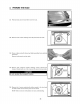
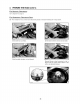
3. PREPARETHE HOOD 3.1 Pull latch tabs and remove filters from the hood. ! sc°Ew O LOCATIONS 3.2 Remove both screws retaining each side panel and set aside. HO0160 3.3 Press on tabs and pull to disconnect light assemblies from electrical harnesses. Remove both panels and set aside. 3.4 Remove both transport bracket retaining screws. Discard the transport bracket and one of its screw (set the second screw aside). Do not reinstall the transport bracket. HO0167 3.
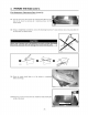
3. PREPARE THE HOOD (CONT'D) FOR VERTICAL DISCHARGE: Go to step 3.11 on page 8. FOR HORIZONTAL DISCHARGE ONLY: 3.6 From inside the hood, remove and discard the olastic air deviator following the 4 steps below. Unfold both fan scroll tabs. Lift the blower wheel to remove and set aside. Slide the plastic deviator out and discard. Reinstall blower wheel ensuring its tab is aligned with the yellow sticker affixed on the motor. (As illustrated below.
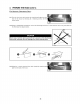
3. PREPARE THE HOOD (CONT'D) FOR HORIZONTAL DISCHARGE ONLY (CONT'D): 3.7 Turn the hood over and remove the metal shutoff plate from the back of the hood, by removing its 3 retaining screws. Set the screws aside. 3.8 Using a straight-blade screwdriver, remove the discharge knock-out. To ease removal, use a long nose pliers for the third step. See figures below. Never use a hammer and a screwdriver to punch out the discharge knock-out, because this will damage the hood internal parts. O HRO066 3.
3. PREPARE THE HOOD (CONT'D) FOR VERTICAL DISCHARGE ONLY: 3.11 Turn the hood over and remove the metal shutoff plate from the back of the hood, by removing its 3 retaining screws. Set the screws aside. 3.12 Using a straight-blade screwdriver, remove the discharge knock-out. To ease removal, use a long nose pliers for the third step. See figures below. Never use a hammer and a screwdriver to punch out the discharge knock-out, because this will damage the hood internal parts. HRO067 O 0 HRO066 3.
4. INSTALLTHEADAPTER/DAMPER The wall duct must be roughed-in to properly interface with the hood. Before performing the installation, make sure the adapter fits easily in the duct. If this hood replaces an existing hood, please note that location of the air exhaust can vary from one hood manufacturer to another. NOTE: If using the optional 3W' x 14" to 3W' x 10" adapter/damper model T461, discard the provided adapter/damper and perform step 4 with the optional adapter/damper model T461.
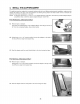
5. INSTALLTHE HOOD 5.1 Run power cable to installation location. Position the hood in its intended location. Using a pen, mark the position of the screws (smaller part of the keyholes, see pictures below for the 5 keyholes locations). Remove the hood. 5.2 Install 4 no. 8 x 1/2" screws, leaving a 1/8" gap (do not install the no. 5 screw yet). HD0403 5.3 Attach the wire clamp, insert the power cable in the hood.
7. REINSTALLBOTTOMPANEL Ensure not to pinch the wires when reinstalling Remove protective plastic film covering filters the bottom panel. before installing them. 7.1 Reinstall the bottom panel, using 9 screws saved from steps 3.4 and 3.5, as shown beside. NOTE: The left side panel will hide one screw. 7.2 Reconnect light assemblies. Reinstall side panels using 4 screws saved from step 3.2. 7.3. Reinstall filters. Do not reinstall the transport bracket. HD0404 8.
9. OPERATION Always turn your blower on before you begin cooking to establish an air flow in the kitchen. Let the blower run for a few minutes to clear the air after you turn off the range. LB 1 t_c A) Blower Delay switch B) ON blower/Speed control switch C) OFF blower/Filter maintenance switch A. BLOWER L_o LE D) OFF lighting E) Halogen light switch DELAY SWITCH: When a speed is selected, press the delay switch to activate the delay function.
IO. USEAND CARE Grease filters and bottom panel. The grease filters and the bottom panel should be cleaned frequently. Use a warm detergent solution. Remove grease filters by pushing them towards the back of hood and rotating downward. Clean all-metal filters in the diswasher using a non-phophate detergent. Discoloration of the filter may occur if using phosphate detergents, or as a result of local water conditions -- but this will not affect filter performance.
11. WIRING DIAGRAM Risk of electrical shock. Electrical wiring must be done by qualified personnel in accordance with all applicable codes and standards. Before connecting wires, switch power off at service panel and lock service disconnecting means to prevent power from being switched on accidentally.
12.
13. WARRANTY ONE YEAR LiMiTED WARRANTY FOR BROAN ELITE PRODUCTS Broan-NuTone LLC (Broan-NuTone) warrants to the original consumer purchaser of Broan Elite products that such products will be free from defects in materials or workmanship for a period of one year from the date of original purchase. THERE ARE NO OTHER WARRANTIES, EXPRESS OR IMPLIED, INCLUDING, BUT NOT LIMITED TO, IMPLIED WARRANTIES OR MERCHANTABILITY OR FITNESS FOR A PARTICULAR PURPOSE.
GUIDE D'INSTALLATION ® LE 661 Z:_CON(_UE POUR USAGE RI_SIDENTIEL SEULEMENTZ_ INSTALLATEUR • LAISSER CE GUIDE AU PROPRI¢:TAIRE. PROPRI¢:TAIRE • DIRECTIVES D'UTILISATION ET D'ENTRETIEN AUX PAGES 28 ET 29. Broan=NuTone LLC; Hartford, Wisconsin www.broan.com 1 800 558-1711 ENREGISTREZ VOTRE PRODUIT EN UGNE ,&."www.broan.com/register SV09440 rev.
Z AVERTISSEMENT Z AVERTISSEMENT AFIN DE DIMINUER LES RISQUES D'INCENDIE, D'ELECTROCUTION OU DE BLESSURES, SUIVEZ LES DIRECTIVES SUIVANTES : N'utilisez cet appareil que de la fa£on pr6vue par le manufacturier. Si vous avez des questions, contactez ce dernier & I'adresse et au num6ro de t616phone indiqu6s sur la garantie. 2. Avant de r6parer ou de nettoyer I'appareil, coupez le courant au panneau d'alimentation et verrouillez-en I'acc_s afin d'6viter sa remise en marche accidentelle.
TABLEDES MATII RES 1. INSTALLATIONDES CONDUITS ....................................................... 19 2. PREPARATIONDE L'INSTALLATION .................................................... 20 3. PREPARATIONDE LA HOTTE ..................................................... 4. INSTALLATIONDE L'ADAPTATEUR/VOLET................................................ 5, INSTALLATION 6. BRANCHEMENTELECTRIQUE ....................................................... 26 7.
2.
3. PRI PARATIONDE LA HOTTE 3.1 Tirer sur le Ioquet des filtres pour les retirer de la hotte. ! O 3.2 Retirer les 2 vis de retenue de chaque panneau mettre de c6t6. lat6ral et les H00160 3.3 Appuyer sur les languettes et tirer afin de d6brancher assemblages lumi_re de leur hamais 61ectrique. les Retirer les panneaux et les mettre de c6t6. EMPLACEMENT 3.4 Retirer les deux vis de retenue du support de transport. Se d6faire du support ainsi que d'une de ses vis (mettre la seconde vis de c6t6).
3. PRI_PARATIONDE LA HOTTE(SUITE) EVACUATION VERTICALE " Passer & I'@ape 3.11 & la page 24. EVACUATION HORJZONTALE SEULEMENT " 3.6 De I'int@ieur de la hotte, retirer le d6viateur en plastique et s'en d6faire. Voir les 4 @apes et ci-dessous. Soulever la roue afin de la retirer et la mettre de c6t& D6plier les deux pattes de la volute. Glisser le d6viateur en plastique hors de son emplacement et s'en d6faire.
3. PRI_PARATION DE LA HOTTE (SUITE) EVACUATION HORIZONTALE SEULEMENT (SUITE) " 3.7 Retourner la hotte et d6visser les 3 vis retenant la plaque m6tallique & I'arri_re de la hotte. Mettre les vis et la plaque de c6t6. 3.8 _, I'aide d'un tournevis & lame plate, retirer I'ouverture pr6amorc6e. Afin d'en faciliter le retrait, utiliser une pince & long bec Iors de la troisi_me 6tape. Voir les illustrations ci-dessous. I'ouverture pr6amorc6e, internes de la hotte.
3. PRI_PARATIONDE LA HOTTE(SUITE) F:VACUATION VERTICALE SEULEMENT " 3.11 Retourner la hotte et d6visser les 3 vis retenant la plaque m@allique & I'arri@e de la hotte. Mettre les vis et la plaque de cSt& 3.12 A I'aide d'un tournevis a lame plate, retirer I'ouverture pr6amorc_e. Afin d'en faciliter le retrait, utiliser une pince long bec Iors de la troisi_me @ape. Voir les illustrations ci-dessous. pr_amorc_e, internes de la hotte. car ceci endommagera les pi_ces HR0067 O HR0068 3.
4. INSTALLATIONDE L'ADAPTATEUR/VOLET Le conduit doit 6tre bien pr6par6 pour recevoir I'adaptateur. Avant d'installer la hotte, s'assurer que I'adaptateur entre ais6ment & I'int6rieur du conduit. Si cette hotte en remplace une autre, veuillez noter que I'emplacement de la sortie de I'air peut varier d'un manufacturier & I'autre.
5. INSTALLATIONDE LA HOTTE 5.1 Passer I'alimentation _lectrique jusqu'& I'endroit de I'installation. Placer la hotte & son emplacement. ,_ I'aide d'un crayon, marquer la position des vis (petite partie des trous en forme de poire, voir les photos ci-dessous pour I'emplacement des 5 trous). Enlever la hotte. 5.2 Visser 4 vis n° 8 x 1/2 po en laissant un espace de 1/8 po (ne pas installer tout de suite la vis n° 5). 4 HD0403 5.
7. REINSTALLATIONDU PANNEAUINFERIEUR Ne pas coincer les fils Iors de la r6installation du panneau inf6rieur. Avant d'installer les filtres, retirer le film protecteur de plastique. 7.1 R6installer le panneau inf6rieur et le fixer & la hotte & I'aide des g vis pr6c6demment retir6es aux 6tapes 3.4 et 3.5, tel qu'il est illustr6 ci-contre. NOTE:Une des vis sera dissimul6e par le panneau lat6ral gauche. 7.2 Rebrancher les assemblages lumi_re.
9. FONCTIONNEMENT Toujours mettre en marche la hotte avant de commencer la cuisson afin d'6tablir une circulation cuisine. Aussi, laisser la hotte fonctionner quelques minutes apr_s I'arr6t de la cuisini_re afin d'a6rer. OOOO d'air dans la OOO 1 LE LB A) Commande B) Commande C) Commande A.
10. ENTRETIEN Filtres et panneau inf6rieur : Les filtres et le panneau inf6rieur doivent 6tre nettoy6s r6guli@ement. Utiliser de I'eau chaude additionn6e de d6tergent. Pour retirer les filtres, tirer sur leurs Ioquets en les poussant vers I'arri@e de la hotte et les d6sengager de celle-ci. Nettoyer les filtres m6talliques au lave-vaisselle avec un d6tergent sans phosphate.
11. SCH#MA#LECTRIQUE Risque d'_lectrocution. Le raccordement _lectrique dolt _tre effectu_ par du personnel qualifi_ conforrn_ment aux codes et aux standards. Avant d'effectuer le branchement, coupez I'alimentation _lectrique au panneau de service et verrouillez-le pour _viter une raise en marche accidentelle.
12. PII CES DE RECHANGE MOD_-LE E661 PIECES DE REMPLACEMENT 1 2 .
13. GARANTIE GARANTIE LIIVIITi_E DE UN AN DES PRODUITS BROAN ELITE Broan-NuTone LLC (Broan-NuTone) garantit _ I'acheteur consommateur initial des produits Broan Elite qu'ils sont exempts de tout d6faut dans les mati@es premi@es ou la main-d'oeuvre, pour une p@iode de un an & compter de la date d'achat par le consommateur initial.
INSTRUCCIONES DE INSTALACION ® ODELO z_EXCLUSIVAMENTE PARA COClNAS DOME_STICASz_ INSTALADOR: ENTREGUE ESTE MANUAL AL PROPIETARIO DE LA CASA. PROPIETARIO: INFORMACION SOBRE UTILIZACION Y CUIDADO EN LAS P,_GINAS 44 Y 45. Broan=NuTone LLC; Hartford, Wisconsin www.broan.com 1-800-558-1711 REGISTRE SU PRODUCTO EN LiNEA EN: www.broan.com/register SV09440 rev.
ADVERTENCIA ADVERTENCIA PARA REDUCiR EL RIESGO DE iNCENDIO, DESCARGA ELECTRICA, O LESION CORPORAL, RESPETE LAS SIGUIENTES INDiCAClONES: 1. 2. 3. 4. 5. 6. 7. Utilice esta unidade 0nicamente de la forma en que indica el fabricante. Si tiene calquier pregunta, p6ngase en contacto con el fabricante en la direcci6n o el tel6fono que aparacen en la garantia. Antes de reparar o limpiar el aparato, ap_.
iNDICE 1. 35 INSTALACION DE LA TUBERiA ..................................................... 2. PREPARACION DE LA INSTALACION 3. PREPARACION DE LA CAMPANA ................................................... ................................................ 36 37-40 4. INSTALACION DEL ADAPTADOR .................................................... 41 5. INSTALACION DE LA CAMPANA .................................................... 42 6. CONEXION 42 DEL CABLEADO .................................
2. PREPARACIONDE LAINSTALACION Compruebe que el aparato viene con los elementos siquientes: Campana Accesorios: • Filtros (2 para las campanas de 30" y 36" de ancho; 3 para la campana • Desviador de corriente (junto la campana) • Adaptador 3W'x • Bolsa con piezas (en una tapa blanca que protegida la campana), que comprende: 14" (en una tapa blanca que protegida la campana) 1 abrazadera de cable, 6 tornillos n.° 8 de 1/2", 2 conectadores • de 42" de ancho) de hilos y 3 tornillos estandar n.
3. PREPARACIONDE LACAMPANA 3.1 Saque los filtros de la campana tirando de la leng0etas. ! O 3.2 Quite los tornillos que sujetan cada tablero lateral y p6ngalos a un lado. H00160 3.3 Presione en las pestaffas y jale para desconectar la luz de los cableados el6ctricos. los conjuntos de Quite ambos tableros y p6ngalos a un lado. 3.4 Quite los tornillos que sujetan el soporte para transporte. Deseche el soporte y uno de los tornillos (conserve el segundo tornillo).
3. PREPARACIONDE LA CAMPANA(CONTINUACION) SOLO PARA EVACUATI6N VERTICAL: Vaya a la etapa 3.11 en la p_.gina 40. SOLO PARA EVACUATION HORIZONTAL: 3.6 Retire y deseche el desviador de pl&stico del aire desde el interior de la campana siguiendo las 4 etapas que se muestran abajo. Despliegue las lengOetas de deslizamiento del ventilador. Levante la rueda del ventilador y p6ngala a un lado. para quitarla Saque el desviador de pl&stico y des6chelo.
3. PREPARACIONDE LA CAMPANA(CONTINUACION) SOLO PARA EVACUATI6N HORIZONTAL (CONTINUACI6N): 3.7 Voltee la campana y quite la placa metalica de cierre de la parte trasera de la campana retirando sus 3 tornillos de retenci6n. Ponga los tornillos a un lado. 3.8 Utilice un destomillador de punta plana recta para quitar la pieza desmontable de descarga. Para que resulte mAs f_.cil, use unos alicates de boca alargada para la tercera etapa. V6anse las ilustraciones abajo.
3. PREPARACIONDE LA CAMPANA(CONTINUACION) SOLO PARA EVACUATI6N VERTICAL: 3.11Voltee la campana y quite la placa metalica de cierre de la parte trasera de la campana retirando sus 3 tornillos de retenci6n. Ponga los tornillos a un lado. 3.12Utilice un destomillador de punta plana recta para quitar la pieza desmontable de descarga. Para que resulte m&s f_.cil, use unos alicates de boca alargada para la tercera etapa. V6anse las ilustraciones abajo.
4. INSTALACIONDELADAPTADOR La tuberfa de pared debe estar bien preparada para colocar en ella el adaptador. Antes de efectuar la instalaci6n, compruebe que el adptador entra bien en la tuberfa. Si la campana que esta instalado sustituye a otra, tenga en cuenta que el lugar de la evacuaci6n del aire puede cambiar de un fabricante a otro.
5. INSTALACIONDE LACAMPANA 5.1 Llieve el cable de alimentaci6n hasta el lugar de la instalaci6n. Coloque la campana en su lugar. Marque con un I&piz el lugar de los tomillos (parte m&s pequeSa de los agujeros, v6anse la ilustraci6n de abajo para los 5 agujeros). Saque la campana. 5.2 Instale 4 tornillos n.° 8 de 1/2" dejando un espacio de 1/8" (no instalar enseguida 5.
7. INSTALACIONDELTABLEROINFERIOR Procure no pellizcar los hilos al volver a instalar el tablero inferior. Retire la pelfcula protectora de pl_stico que cubre los filtros antes de instalarlos. 7.1 Vuelva a instalar el tablero inferior con los 9 tornillos que guard6 de las etapas 3.4 y 3.5, como se ve en la ilustraci6n. NOTA: El tablero lateral izquierdo tapar_ un tornillo. 7.2 Vuelva a conectar los conjuntos de las hces.
9. FUNClONAMENTO Ponga en marcha siempre el ventilador antes de empezar a cocinar para generar una corriente de aire en la cocina. Deje en marcha el ventilador durante unos minutos para renovar el aire una vez que haya apagado la cocina. @@@@ HC0016 L A JNTERRUPTOR Lc LB A) Interruptor de retardo del ventilador B) Encendido/Oontrol de velocidad del ventilador C) Interruptor de apagado del ventilador/Mantenimiento A.
10. UTILIZACIONY CUIDADO Filtros de grasa y tablero inferior Los filtros de grasa y el tablero inferior deben limpiarse con frecuencia. Utilice una disoluci6n templada. Retire los filtros empujado hacia parte trasera de la campana y gir_ndolos hacia Limpie los filtros completamente met_licos en el lavaplatos con undetergente sin fosfatos. puede ocurrir si se utilizan detergentes con fosfato o como resultado de la condici6n del afectara el rendimiento del filtro.
11. DIAGRAMAELI_CTRICO Riesgo de choque el6ctrico. La conexi6n el6ctrica debe hacerla personal competente con arreglo a los c6digos y normas en vigor. Antes de conectar los hilos, corte la alimentaci6n en el tablero de servicio y bloquee los medios de desconexi6n para impedir que la corriente se conecte accidentalmente.
12. PIEZAS MODELO E661 i! !iiiiiiiii!ii!i! i! ii!i ii Para que la campana se conserve SUSTITUClON 1 2 SV14971 SV09225 3 4 5 6 SV01766E SV05917 SV09435 SV09434 7 SV05921 SV06244 SV06264 SV02160 SV07325 SV06750 SV06252 SV09440 8 9 10 11 12 * ADAPTADOR CONTROLELECTRONICO MOTOR(CON RUEDA_ CUBIERTADE L,4MPARA SOPORTEDE CUBIERTA DE L,4MPARA ANILLO L_,MPARAHALOGENA (50 W, 120 V, GU10 FILTROS9.922"X 17.981" FILTROS12.922"X 17.
13. GARANTiA GARANTJA LIMITADA DE UN ANO DE LOS PRODUCTOS BROAN ELITE Broan-NuTone LLC (Broan NuTone) garantiza al consumidor comprador original de sus productos que dichos productos carecen de defectos en los materiales o de mano de obra por un periodo de un aSo a partir de la fecha de compra original. NO EXlSTEN OTRAS GARANTiAS, EXPRESAS O IMPLICITAS, INCLUYENDO -AUNQUE SIN LIMITARSE A ELLAS -- LAS GARANTiAS IMPLiCITAS, DE APTITUD O IDONEIDAD PARA UN PROPOSITO PARTICULAR.