INSTALLATION GUIDE IN THIS REVISION: New information about extended defrost setting on page 16. IMPORTANT NOTES 1. The one and only main wall control compatible with these units is the VT9W wall control. 2. These units have a new balancing procedure, see Section 7. 3. The terminal connectors for these units are not in the installation kit; they are already mounted to their control board.
ABOUT THIS GUIDE Because of the large amount of models covered in this publication, the illustrations are typical ones. Some details of your unit may be slightly different than the ones shown. Please take note that this guide uses the following symbols to emphasize particular information: ! WARNING Identifies an instruction which, if not followed, might cause serious personal injuries including possibility of death.
TABLE OF CONTENTS 1. SERVICE PARTS ...............................................................................................................................................................4-5 2. AIR DISTRIBUTION ...............................................................................................................................................................6 3. INSTALLATION .....................................................................................................................
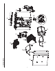
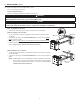
VL0071 G 1.
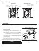
SV63436 SV63438 1 1 1 1 1 1 1 1 1 1 1 1 1 HRV CORE FILTER (PAIR) ERV CORE FILTER (PAIR) HEAT RECOVERY CORE ENERGY RECOVERY CORE DOOR ASSEMBLY (INCLUDING NO. 16) RIGHT PANEL ERV CORE FILTER (PAIR) ENERGY RECOVERY CORE DAUGHTER BOARD (INCLUDING INO. 11) PCB CONNECTOR (MAIN CONTROL) PCB CONNECTOR (AUXILIARY CONTROL) PCB (INCLUDING NOS.
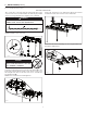
2. AIR DISTRIBUTION NORMAL OPERATION STALE AIR FRESH AIR STALE AIR FROM OUTDOORS FROM BUILDING DEFROST OR RECIRCULATION STALE AIR FILTERED AIR FROM BUILDING TO BUILDING FRESH AIR TO OUTDOORS TO BUILDING VF0063 3. INSTALLATION 3.1 INSPECT THE CONTENT OF THE BOX Inspect the exterior of the unit for shipping damage. Ensure that there is no damage to the door, ports, power cord, etc. 3.2 LOCATING THE UNIT UNIT HUNG BY CHAINS AND SPRINGS Choose an appropriate location for the unit.
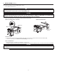
3. INSTALLATION (CONT’D) 3.2 LOCATING THE UNIT (CONT’D) UNIT HUNG TO WALL BRACKET Trace a level line on the wall; align the wall bracket (the longer Lift the unit and hang it to the wall bracket. Ensure the bracket one) to the line and secure this bracket to the wall using 4 provided assembled on back of the unit rests on the wall bracket. screws (1½” long) and washers, if using the slots on bracket). ! WARNING Ensure the wall bracket is attached to all of the available studs, not into the drywall alone.
3. INSTALLATION (CONT’D) 3.3 PLANNING OF THE DUCTWORK • Keep it simple. Plan for a minimum of bends and joints. • Keep the length of insulated and non-insulated ducts to a minimum, because the length of the ductwork impacts directly the unit airflow performances. • Do not ventilate crawl spaces or cold rooms. Do not attempt to recover the exhaust air from a dryer or a range hood. This would cause clogging of the filters and recovery module.
3. INSTALLATION (CONT’D) 3.5 INSTALLING THE DUCTWORK AND REGISTERS (CONT’D) 3.5.2 CENTRAL DRAW POINT SYSTEM Stale air exhaust ductwork Same as for Fully Ducted System, described on point 3.5.1 ! WARNING When performing duct connections, always use approved tools and materials. Respect all corresponding laws and safety regulations. Please refer to your local building code.
3. INSTALLATION (CONT’D) 3.5 INSTALLING THE DUCTWORK AND REGISTERS (CONT’D) 3.5.3 SIMPLIFIED INSTALLATION ! WARNING When performing duct connections, always use approved tools and materials. Respect all corresponding laws and safety regulations. Please refer to your local building code. CAUTION When performing duct connections to the furnace supply duct (Method 1), this duct must be sized to support the additional airflow produced by the unit. Also, the use of metal duct is highly recommended.
3. INSTALLATION (CONT’D) 3.6 CONNECTING THE DUCTS TO THE UNIT NOTE: All unit ports are were created to be connected to ducts having a minimum of 6” diameter, but if need be, they can be connected to bigger sized ducts by using an appropriate transition (e.g.: 6” diameter to 7” diameter transition). Insulated flexible ducts Use the following procedure to connect the insulated flexible ducts to the ports of the unit (Exhaust air to outdoors and Fresh air from outdoors ports).
3. INSTALLATION (CONT’D) 3.7 INSTALLING TWO EXTERIOR HOODS Choose an appropriate location to install the exterior hoods: • There must be a minimum distance of 6 feet between EXHAUST HOOD the hoods to avoid cross-contamination. • There must be a minimum distance of 18 inches from the ground.
4. CONTROLS 4.1 UNIT BOOTING SEQUENCE The unit booting sequence is similar to a personnal computer boot sequence. Each time the unit is plugged after being unplugged, or after a power failure, the unit will perform a 30-second booting sequence before starting to operate. During the booting sequence, the unit is checking and resetting the motorized damper position. Once the motorized damper position completely set, the booting sequence is done. NOTE: No command will be taken until the unit is fully booted.
4. CONTROLS (CONT’D) 4.2 WALL CONTROL(S) ELECTRICAL CONNECTION (CONT’D) 4.2.1 TERMINAL BLOCK(S) CONNECTION MAIN CONTROL TERMINAL BLOCK AUXILIARY CONTROL TERMINAL BLOCK Strip the end of the main control cable to access the 4 wires. Strip the end of each wire. Using a small flat blade screwdriver, connect each wire to its corresponding terminal, by referring on the sticker affixed on the unit: YELLOW wire to “Y”, BLACK wire to “B”, RED wire to “R” and GREEN wire to “G”.
4. CONTROLS (CONT’D) 4.2 WALL CONTROL(S) ELECTRICAL CONNECTION (CONT’D) 4.2.2 ELECTRICAL CONNECTION TO VB60W OPTIONAL AUXILIARY CONTROL(S) Up to five (5) VB60W auxiliary controls can be installed. VE0349 CONT When used, the VB60W activation will override the main control operation, as well as the unit defrost cycle.
4. CONTROLS (CONT’D) 4.3 SETTING UNIT OPERATION IN THE REMAINING 40 MINUTES ON 20 MIN/H MODE AND SETTING UNIT DEFROST CYCLE TYPE USING VT9W MAIN WALL CONTROL CAUTION Set extended defrost on all units located in climates where the outdoor temperature typically remains below -13°F (i.e. Bemidji, MN; Duluth, MN; Fargo, ND; Fairbanks, AK) over a 24-hour period for several days in a row, combined with an indoor humidity of 40% or higher. 3 sec. MODE Press and hold the MODE key for 3 seconds.
5. ELECTRICAL CONNECTION TO THE FURNACE ! WARNING Never connect a 120-volt AC circuit to the terminals of the furnace interlock (standard wiring). Only use the low voltage class 2 circuit of the furnace blower control. For a furnace connected to a cooling system: On some older thermostats, energizing the “R” and “G” terminals at the furnace has the effect of energizing “Y” at the thermostat and thereby turning on the cooling system.
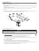
G Power cable G Power cable to A1-J17 Control cable 1 2 3 1 2 3 F1 J8 J9 MED HI 3 2 1 5 4 3 2 1 W1 J10 W G B 12 J13 A3 J2 J14 4 3 2 1 J3 6 5 4 3 2 1 R2 Override switch (optional; see notes 3 & 4) G R B Y Field wiring remote control (see notes 3 & 4) Furnace blower interlock J14-1: NO J14-2: COM J14-3: nc (optional; see notes 3 & 5) t˚ Thermistor R1 COLOR CODE B BLACK BL BLUE BR BROWN G GREEN R RED WHITE W Y YELLOW nc no connection Line voltage factory wiring Class 2 low vo
7. BALANCING THE UNIT 7.1 WHAT YOU NEED TO BALANCE THE UNIT • • • One VT9W main wall control close to the unit. A magnehelic gauge capable of measuring 0 to 0.5 inch of water (0 to 125 Pa) and 2 plastic tubes. The balancing chart of the unit. 7.2 PRELIMINARY STAGES TO BALANCE THE UNIT • • • Seal all the unit ductwork with tape. Close all windows and doors. Turn off all exhaust devices such as range hood, dryer and bathroom fans.
7. BALANCING THE UNIT (CONT’D) 7.4 BALANCING CHART AND PRESET SPEEDS TABLE (CONT’D) Use the balancing chart to convert pressure (in. w.g.) values read from magnehelic gauge to airflow (CFM) values. While balancing, the VT9W wall control screen shows which pressure taps have to be used. See example below. UNIT BALANCING CHART Plug magnehelic gauge tubing to STALE airflow. Plug magnehelic gauge tubing to FRESH airflow. FLOW FRESH STALE CFM IN. W.G. IN. W.G. 120 0.71 0.73 125 0.67 0.70 130 0.
7. BALANCING THE UNIT (CONT’D) 7.5 BALANCING PROCEDURE B Connect an VT9W main wall control nearby the unit. GENERAL INFORMATION ABOUT VT9W WALL CONTROL USAGE IN UNIT BALANCING PROCEDURE MODE Press on MODE key to raise the value. % HUM Press on % HUM key to accept. TURBO Press on TURBO key to lower the value. PROG flashes on screen as long as you are in Program Mode Setting menus (preset speeds or custom speeds).
7. BALANCING THE UNIT (CONT’D) BALANCING PROCEDURE (CONT’D) F If the unit speed is set close to its highest speed, we recommend to first measure and note both airflows. G Refer to the unit balancing chart to find the corresponding CFMs. H Determine which airflow should be adjusted (the higher airflow must be lowered to equalize the lower one). See example below. Pressure in. w.g. Fresh CFM Stale CFM 0.31 152 155 0.32 156 159 0.33 159 162 0.34 162 166 0.35 165 169 0.36 168 172 0.
7. BALANCING THE UNIT (CONT’D) BALANCING PROCEDURE (CONT’D) J Adjust fresh air TURBO speed (or press % HUM key to keep it as is). TURBO Write selected airflow percentage % HUM on label affixed on the unit for future Press % HUM key reference. to accept chosen percentage. MODE TURBO Install tubing on fresh airflow pressure taps and take the reading. Press on MODE key to raise the value. Press on TURBO key to lower the value.
7. BALANCING THE UNIT (CONT’D) BALANCING PROCEDURE (CONT’D) L Set VB60W control speed. Plug magnehelic gauge tubing to STALE airflow. NOTE: According to the installation, the magnehelic gauge tubing can be connected to exhaust OR supply air flow. The arrow on screen will shown which airflow will have to be set. Plug magnehelic gauge tubing to FRESH airflow. Write selected airflow percentage % HUM on label affixed on the unit for future Press % HUM key reference to accept chosen percentage.
8. TROUBLESHOOTING ! WARNING Risk of electric shocks. Electronic board connections must be checked by qualified personnel only. If the unit does not work properly, reset the unit by unplugging and then replug it. If it is still not working properly, refer to the table below. If the LED of the unit is flashing, this means the unit sensors have detected a problem. See the table below to know where the problem occurs on the unit.
8. TROUBLESHOOTING (CONT’D) PROBLEMS POSSIBLE CAUSES 1 The error code E01 is displayed on VT9W wall control screen. • The wires may be in reverse position. • Ensure that the color coded wires have been connected to their appropriate places. • The wires may be misconnected. • Ensure the wires are correctly connected. • The wires may be broken. • Inspect every wire and replace any damaged ones. If wires are hidden into walls, test the control using a shorter wire.
8. TROUBLESHOOTING (CONT’D) PROBLEMS POSSIBLE CAUSES YOU SOULD TRY THIS The damper system does not work (LED flashes AMBER, error code E23). At power up, no RED LED. • See point 4. At power up, LED lights RED and there is a clicking sound coming from electrical compartment, but damper does not move: • Ice or other things hindering the damper movement. • J12 unconnected or bad contact. • Wrong connection of J8. • The transformer may be defective (no 24 VAC between J8-1 and J8-2).
NOTES 28
MANUAL DE INSTALACIÓN EN ESTA REVISIÓN encontrará información nueva sobre la configuración de la descongelación ampliada (pág. 16). NOTAS IMPORTANTES 1. El único control mural compatible con estas unidades es el control mural VT9W. 2. Estas unidades están sujetas a un nuevo procedimiento de equilibrado. Véase la Sección 7. 3. Los conectores de terminales de estas unidades no vienen con el kit para la instalación; ya están montados en su placa de control electrónico.
ACERCA DE ESTE MANUAL Dado el gran número de modelos de los que trata este manual, las ilustraciones son de carácter general. Algunos detalles de su aparato pueden ser ligeramente distinos de los que se muestran aquí. Con el fin de hacer hincapié en determinada información, en este manual se emplean los siguientes símbolos: ! ADVERTENCIA Se refiere a una instrucción que, de no siguirse podría causar heridas corporales graves e incluso la muerte.
ÍNDICE 1. PIEZAS ..........................................................................................................................................................................4-5 2. DISTRIBUCIón DEL AIRE ........................................................................................................................................................6 3. INSTALACIóN ...............................................................................................................................
4 VL0071 1.
5 2 1 1 1 CONJUNTO DEL VENTILADOR IMPELENTE (INCLUYE 3 TORNILLOS DE PLÁSTICO) FILTRO DEL NúCLEO RECUPERADOR DE CALOR HRV (PAR) FILTRO DEL NúCLEO RECUPERADOR DE ENERGíA ERV (PAR) NúCLEO DE RECUPERACIóN DE CALOR 3 1 1 1 1 1 CONECTOR DE LA PLACA DE CIRCUITOS IMPRESOS (PCB) (CONTROL AUXILIAR) CONECTOR DE LA PLACA DE CIRCUITOS IMPRESOS (PCB) (INCLUYE LOS ÍTEMS 10 Y 12) TRANSFORMADOR KIT DEL TERMISTOR DEL LADO CALIENTE* INTERRUPTOR MAGNÉTICO DE PUERTA* TORNILLO DE PLÁSTICO (JUEGO DE 6)* KIT DE PIEZA
2. DISTRIBUCIÓN DEL AIRE FUNCIONAMIENTO NORMAL DESHIELO O RECIRCULACIóN AIRE FRESCO AIRE FILTRADO AIRE VICIADO DESDE EL AIRE DE SALIDA HACIA EL EXTERIOR DEL EDIFICIO AIRE DE SALIDA DEL EDIFICIO AIRE PURO DE DE ENTRADA EN EL EDIFICIO ENTRADA EN EL EXTERIOR EDIFICIO VF0063 3. INSTALACIÓN 3.1 EXAMEN DEL CONTENIDO DE LA CAJA Examine el exterior del aparato para ver si hay daños debidos al envío. Compruebe que la puerta, los pestillos, el cable de alimentación, etc., no estén dañados. 3.
3. INSTALACIÓN (CONTINUACIÓN) 3.2 UBICACIóN DEL APARATO (CONTINUACIóN) UNIDAD COLGADA AL SOPORTE MURAL Trace una línea a nivel en la pared; alinee el soporte mural (el más largo) con la línea y fije el soporte a la pared con los 4 tornillos (1½’’ de largo) y las arandelas provistos, si se usan los huecos del soporte). ! ADVERTENCIA Levante la unidad y cuélguela al soporte mural. Compruebe que el soporte instalado en la parte trasera de la unidad reposa en el soporte mural.
3. INSTALACIÓN (CONTINUACIÓN) 3.3 PLANIFICACIóN DE LOS TUBOS • Intente hacer una instalación sencilla. Prevea la menor cantitad posible de tubos curvados y juntas. • Utilice conductos aislados de una longitud mínima ya que dicha longitud influye directamente en el rendimiento de las corrientes de aire de la unidad. • No ventile sótanos ni cuartos fríos. No intente recuperar el aire de salida de una secadora o de una campana de cocina. De hacerlo, podrían obstruirse los filtros y el módulo de recuperación.
3. INSTALACIÓN (CONTINUACIÓN) 3.5 INSTALACIóN DE LOS TUBOS Y REGISTROS (CONTINUACIóN) 3.5.2 SISTEMA DE VENTILACIó EN PUNTO DE ORIGEN Tubo de extracción de aire viciado Siga la misma indicaciones que cuando se trata de un sistema totalmente entubado, descrito en la sección 3.5.1 ADVERTENCIA Utilice siempre herramientas y materiales homologados para conectar los tubos. Aténgase a todas las leyes y reglementos de seguridad correspondientes. Consulte el código de construcción local.
3. INSTALACIÓN (CONTINUACIÓN) 3.5 INSTALACIóN DE LOS TUBOS Y REGISTROS (CONTINUACIóN) 3.5.3 INSTALACIóN SENCILLA ! ADVERTENCIA Utilice siempre herramientas y materiales homologados para conectar los tubos. Aténgase a todas las leyes y reglementos de seguridad correspondientes. Consulte el código de construcción local.
3. INSTALACIÓN (CONTINUACIÓN) 3.6 CONEXIÓN DE LOS TUBULOS AL APARATO NOTA: Todas las bocas de los aparatos han sido diseñadas para conectarse a tubos de un diámetro mínimo de 6”, pero de ser necesario, se pueden conectar con tubos de mayor diámetro utilizando un cambio de sección adecuado (p. ej., un cambio de sección de 6” a 7” de diámetro).
3. INSTALACIÓN (CONTINUACIÓN) 3.7 INSTALACIóN DE 2 BOCAS EXTERIORES Eligir un lugar apropiado para to instalar las bocas exteriores: • Es preciso que haya una distancia mínima de 6 pies BOCA DE entre las bocas para evitar la contaminación cruzada. EXPULSIóN • Es preciso que haya una distancia mínima de 18 pulgadas del suelo. 6" Ø (152 MM) LUGAR DE TUBOS BOCA DE OPTATIVO ENTRADA ! ADVERTENCIA 18" (457 MM) Compruebe que la boca de entrada del aire puro se encuentra a una distancia mínima de 6 pies (1.
4. CONTROLES 4.1 SECUENCIA DE PUESTA EN MARCHA La secuencia de puesta en marcha del aparato es similar a la de una computadora personal. Cada vez que se enchufa el aparato despuésde haberlo desenchufado o tras un corte de corriente, el aparato pasára por una secuencia de puesta en marcha de unos 30 segundos antes de empezar a funcionar. Durante la secuencia, el aparato está verificando y tratando de reconfigurar la posición del registro motorizado.
4. CONTROLES (CONTINUACIÓN) 4.2 CONEXIÓN ELÉCTRICA DEL CONTROL O CONTROLES MURALES (CONTINUACIóN) 4.2.1 CONEXIÓN DE LOS BLOQUES DE TERMINALES BLOQUE DE TERMINALES DEL CONTROL PRINCIPAL BLOQUE DE TERMINALES DEL CONTROL AUXILIAR Pele el extremo del cable del control principal para tener acceso a los 4 hilos. Pele el extremo de cada hilo.
4. CONTROLES (CONTINUACIÓN) 4.2 CONEXIÓN ELÉCTRICA DEL CONTROL O CONTROLES MURALES (CONTINUACIóN) 4.2.2 CONEXIÓN ELÉCTRICA CON EL CONTROL O CONTROLES AUXILIARES OPCIONALES VB60W Se pueden instalar hasta cinco (5) controles auxiliares VB60W VE0349 CONT Cuando se use, la activación del control auxiliar VB60W anulará el funcionamiento del control principal así como el ciclo de deshielo de la unidad.
4. CONTROLES (CONTINUACIÓN) 4.3 CONFIGURACIÓN DEL FUNCIONAMIENTO DE LA UNIDAD EN LOS 40 MINUTOS RESTANTES EN EL MODO 20 MIN/H Y CONFIGURACIÓN DEL TIPO DE CICLO DE DESHIELO DE LA UNIDAD MEDIANTE EL CONTROL MURAL PRINCIPAL VT9W. CAUTION Configure la descongelación ampliada en todos los aparatos situados en climas donde la temperatura exterior normalmente permanece por debajo de -13°F (p. ej.
5. CONEXIÓN ELÉCTRICA CON LA CALDERA ! ADVERTENCIA No conecte nunca un circuito de corriente alterna de 120 voltios a los terminales del interbloqueo de la caldera (cableado estándar). Utilice sólo el circuito de clase 2 de bajo voltaje del control del ventilador impelente de la caldera.
V Cable de alimentación V a A1-J17 Cable de alimentación J4 J8 J9 MED ALTA 3 2 1 12 1 2 34 5 J1 J13 J20 12 1 2 34 5 J14 4 3 2 1 J3 6 5 4 3 2 1 t˚ R2 Termistor R1 Interruptor de annulación (opcional; véanse las notas 3 y 4) Cableado in situ del control (véanse las notas 3 y 4) V R NE A Interbloqueo del ventilador impelente de la caldera J14-1: NO J14-2: COM J14-3: sc (opcional; véanse las notas 3 y 5) t˚ Sensor de la temperatura de deshielo A AZ B M N NE R V sc AMARILLO AZUL BLANC
7. EQUILIBRADO DEL APARATO 7.1 ELEMENTOS NECESARIOS PARA EQUILIBRAR EL APARATO • • • Un control mural principal VT9W cerca de la unidad. Un caudalímetro de hélice capaz de medir de 0 pulgada a 0.5 pulgadas de agua (0 Pa a 125 Pa) y 2 tubos de plástico. Cuadro de equilibrado del aparato. 7.2 ETAPAS PRELIMINARES PARA EQUILIBRAR EL APARATO • • • Obture todos los tubos del aparato con cinta. Cierre todas las ventanas y puertas.
7. EQUILIBRADO DEL APARATO (CONTINUACIÓN) 7.4 CUADRO DE EQUILIBRADO Y TABLA DE VELOCIDADES PRESELECCIONADAS (CONTINUACIóN) Use el cuadro de equilibrado para convertir los valores de presión (pulgadas de columna de agua o in. w.g.) del caudalímetro de hélice a valores de corriente de aire (pi3/min). Durante la conversión, la pantalla del control mural principal VT9W muestra las tomas de presión que han de usarse. Véase el ejemplo de abajo.
7. EQUILIBRADO DEL APARATO (CONTINUACIÓN) 7.5 PROCEDIMIENTO DE EQUILIBRADO B Conecte un control mural principal VT9W próximo a la unidad. INFORMACIÓN GENERAL SOBRE EL USO DEL CONTROL MURAL VT9W EN EL PROCEDIMIENTO DE BALANCEO DE LA UNIDAD MODE Presione la tecla MODE para aumentar el valor. % HUM Presione la tecla % HUM para aceptar. TURBO Presione la tecla TURBO para disminuir el valor.
7. EQUILIBRADO DEL APARATO (CONTINUACIÓN) PROCEDIMIENTO DE EQUILIBRADO (CONTINUACIÓN) F Si la velocidad de la unidad está cerca de su velocidad más alta, se aconseja tomar la medida de los dos corrientes de aire y de notarlos. G Consulte el cuadro de equilibrado de la unidad para encontrar el valor pi3/min correspondiente. H Determine la corriente de aire que debe ajustarse (la corriente de aire más alta debe disminuirse hasta igualar a la más baja). Véase el ejemplo de abajo. Presión in. w.g.
7. EQUILIBRADO DEL APARATO (CONTINUACIÓN) PROCEDIMIENTO DE EQUILIBRADO (CONTINUACIóN) J Ajuste la velocidad TURBO del aire viciado (o presione la tecla % HUM para dejarla tal cual). TURBO O TURBO Instale los tubos en las tomas de presión de la corriente de aire fresco y efectúe la medición. Presione la tecla MODE para incrementar el valor. Presione la tecla TURBO para disminuir el valor.
7. EQUILIBRADO DEL APARATO (CONTINUACIÓN) 7.5 PROCEDIMIENTO DE EQUILIBRADO (CONTINUACIóN) L Seleccione la velocidad de control VB60W Enchufe el tubo del caudalímetro de hélice a la corriente de aire VICIADO. NOTA: Según la instalación, el tubo del caudalímetro de hélice puede conectarse a la corriente de aire de salida O de alimentación. La flecha de la pantalla mostrará la corriente de aire que hay que ajustar. Enchufe el tubo del caudalímetro de hélice a la corriente de aire FRESCO.
8. SOLUCIÓN DE PROBLEMAS ! ADVERTENCIA Riesgo de descarga eléctrica. Las conexiones de la tarjeta electrónica sólo deben verificarse por personal cualificado. Si el aparato no funciona debidamente, desenchúfelo durante un minuto y vuélvalo a enchufar para reiniciarlo. Si sigue sin funcionar debidamente, consulte la tabla de abajo. Si el diodo del aparato parpadea es que los sensores han detectado un problema. Vea la tabla siguiente para saber dónde se ha producido dicho problema.
8. SOLUCIÓN DE PROBLEMAS (CONTINUACIÓN) 1 2 3 PROBLEMAS CAUSAS POSIBLES INTENTE ESTO El código de error E01 aparece en la pantalla del control mural VT9W. • Los hilos pueden estar en posición inversa. • Los hilos pueden estar mal conectados. • Los hilos pueden estar rotos. • Compruebe que los hilos con códigos de colores han sido conectados en los lugares adecuados. • Compruebe que los hilos estén bien conectados.
8. SOLUCIÓN DE PROBLEMAS (CONTINUACIÓN) PROBLEMAS CAUSAS POSIBLES INTENTE ESTO El sistema de la clapeta no funciona (la señal LED parpadea en ÁMBAR, código de error E23). Al encender, no hay señal LED ROJA. Al encender, la señal LED se pone en ROJO y hay un sonido de clic proveniente del compartimento eléctrico, pero la clapeta no se mueve: • El hielo o otras cosas obstaculizan el movimiento de la clapeta. • El conector J12 está desconectado o tiene un mal contacto • Conexión errónea del conector J8.
NOTAS 28