BROOKFIELD DIGITAL RHEOMETER MODEL DV-III Operating Instructions Manual No. M/91-210-I297 SPECIALISTS IN THE MEASUREMENT AND CONTROL OF VISCOSITY BROOKFIELD ENGINEERING LABORATORIES, INC. 240 Cushing Street, Stoughton, MA 02072-2398 USA TEL 617-344-4310 or 800-628-8139 (USA ex MA) TLX 200195 FAX 617-344-7141 617-344-7141 INTERNET http://www.brookfieldengineering.
TABLE OF CONTENTS I. INTRODUCTION ........................................................................ 3 1 Components ........................................................................... 3 2 Utilities .................................................................................. 4 3 Specifications ........................................................................ 4 4 Battery Back-Up .................................................................... 5 5 Set-Up .......................
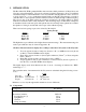
I. INTRODUCTION The Brookfield DV-III Programmable Rheometer measures fluid parameters of Shear Stress and Viscosity at given Shear Rates. Viscosity is a measure of a fluid’s resistance to flow. You will find a detailed description of the mathematics of viscosity in the Brookfield publication “More Solutions to Sticky Problems”, a copy of which was included with your DV-III. The principle of operation of the DV-III is to drive a spindle (which is immersed in the test fluid) through a calibrated spring.
Component Part Number Spindle Set with Case depends on model LVDV-III set of four spindles or SSL RVDV-III set of seven spindles or SSR HA/HBDV-III set of seven spindles SSH For Cone/Plate versions: a spindle wrench, one cone spindle and sample cup Part No. CP-44Y replace the spindle set.
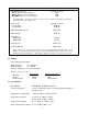
RS232 Compatible Serial Port for use with attached printer or PC. See Appendix H of Brookfield application software program called RHEOCALC. Weight: Gross Weight Net Weight Carton Volume 35 lbs 32 lbs 2.0 cu ft 15.9 kg 14.5 kg .057 m3 I.4 Battery Back-Up When the Rheometer is turned off or there is a power failure, a built-in battery saves spindle parameters (used to calculate centipoise, shear rate and shear stress), default settings and the test data from the last program test run .
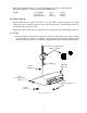
2) Insert the mounting handle on the back of the DV-III into the hole on the clamp assembly (Figure 2). Bubble Level Rack Gear Clamp Screw Clamp Assembly Mounting Handle Upright Rod Figure 2 3) Tighten the DV-III clamp Screw (Figure 2). Note: If the clamp assembly moves along the upright rod too freely, tighten the tension screw (see Appendix F).
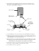
4) Select the ribbon cable end with the adjacent, heavy, black mass. Insert this end of the ribbon cable into the DV-III Rheometer head. Insert the other end of the ribbon cable into the connector on the DV-III base (see Figure 3). Rheometer Head RTD Temperature Probe Connector Ribbon Cable Power ON/OFF Switch Connector RS-232 Serial Printer/Computer Analog Output(s) A.C. Fuse(s) APPROVED POUER SUPPLY TUV RHEINLAND LICENSE NO. R9051346 RECOGNIZED COM,PONENT UL FILE NO.
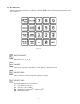
I.6 Key Functions Figure 4 shows the control keys on the face of the DV-III Rheometer. The following describes each key’s function. Figure 4 MOTOR ON/OFF Turns the motor on or off. CANCEL Cancels any operation, and returns screen display to the main screen. SELECT SPDL Allows selection of and accepts the spindle to be used. SELECT DISP Selects the parameter to be displayed: % Viscometer Torque (%) cP Viscosity (cP or mPa.
OPTION Configures the DV-III printer output; changes between °C and °F temperature; sets high and low alarms; displays and/or prints test data; selects either CGS or SI units; sets printer handshakes. CLEAR SPEED Removes a test program from memory. PROG SPEED Constructs a test program. Allows you to review/modify an existing test program. Executes a selected program. PROG RUN Starts a test program, and chooses which steps to run, and in what order.
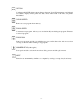
II. GETTING STARTED II.1 Autozero Before readings may be taken, the Rheometer must be autozeroed. This is done each time the power switch is turned on or any time the user chooses.
The starting screen is the main screen display (Figure 6). Pressing the SELECT SPDL key causes the cursor to blink under the field for the first number of the Spindle Entry Code (Figure 7). Figure 7 Enter the two digit code for the spindle you intend to use. Spindle Entry Code numbers are found in Appendix D. Pressing the SELECT SPDL key once more accepts the spindle entered.
III. PROGRAM MODE TESTING The DV-III can store 10 speed set programs and each program may have up to 25 steps. The program locations are numbered 0 through 9. There are two types of test programs: 1) Next Speed Set where the test speeds are programmed, and the operator must signal the DVIII to change speeds (and therefore take a reading) by pressing the NEXT key. 2) Prog Speed Set where the DV-III will perform the test automatically. Each step of a program has two variables - speed and hold time.
9) If the program is to have less than 25 steps, the End Program Entry command is given by entering “0” for the step speed as the final program step. If the program is to have 25 steps, entry is ended automatically after the 25th step. Next Mode Speed Set Notes: a) The NEXT key has three functions: 1) Accept the value just entered. 2) Move the cursor between the speed and time field for the first step. 3) Move from step field to step field.
Example: If the time in step 3 is 30 seconds (00:30), when the display changes (to step 4) 00:30 will appear in the time field as the new default time. You now have two choices: i) The time may be changed to another (01:30, for instance) following steps 4 through 6 above (the new time will overwrite the old time automatically). ii) The default time of 00:30 may be accepted by pressing the NEXT key after the speed entry (to accept the speed) and then the PROG RUN key to move to the next step.
III.4 Using a Speed Set Program from Memory To use a speed set immediately after it is entered, begin with the Program Complete screen shown in Figure 12. Figure 12 1) Press the number 3 key: Use Speed Set. The screen display will be similar to Figure 13. Figure 13 2) Press PROG RUN. The screen in Figure 14 appears. Figure 14 3) Enter the step which will be the starting step. Note that all steps, or just a portion of the steps may be used. Additionally, the steps may be run in reverse order.
Speed Set Usage Notes: 1) When a speed set is used, all the captured test data is stored in memory until another speed set test is run. When the next (either a new or memory resident) speed set test begins, the last captured test data is over-written. 2) After a speed set is executed, the data is retained in memory by the DV-III even if the power switch is turned off. 3) To halt a running program, press the PROG RUN key.
operating in the Lock-Out mode. Figure 17 To review data, print data or exit the Lock-Out mode, you have to disable lock-out. 1) Press the PROG RUN key. 2) Press the OPTION key and the Lock-out Options screen will be displayed. 3) Press NUMBER 3 to disable Lock-Out and the screen changes to the step sequence screen (Figure 14) ready for you to select your step sequence. 4) Press CANCEL and you are returned to the main screen. Refer to Section IV. The Options Menu, for data review and/or printing. III.
key. The speed set program will be printed on the attached printer as shown below. BROOKFIELD DV-III RHEOMETER DATA FOR SPEED SET #1 SPEED SPEED SPEED SPEED SPEED #01 #02 #03 #04 #05 RPM = 30.0 RPM = 40.0 RPM = 50.0 RPM = 60.0 RPM = 70.
IV. THE OPTIONS MENU The OPTION key is used to display the Options Menu screen. The Options Menu provides choices of the following options: OPTIONS MENU 1 PRINT 4 C -> F 2 ALARMS 5 CGS -> SI 3 DATA 6 HSK ON Figure 19 1 - PRINT 2 - ALARMS 3 - DATA 4 - C TO F 5 - CGS TO SI 6 - HKS (ON/OFF) set modes, when a serial printer is attached setting-high, low, and motor On/Off limits review of captured data choice of temperature display choice of CGS or SI units handshake serial printer communication parameter IV.
Figure 20 If the printer is connected correctly, and is “on line”, but does not print, this indicates that the printer is not using the X-on/X-off protocol and HKS should be set to “OFF”. Press the CANCEL key to return to the main screen, then: 1) Press the OPTION key to display the Options Menu. 2) Press the NUMBER 6 key to set HSK to OFF. 3) Press the CANCEL key to return to the main screen. 4) Press the NEXT key to print a line of data.
The print option status is clearly displayed on the main screen at all times. For example, as shown earlier in Figures 6, 8 and 13, “PRTO” indicates that the print mode in these cases is “PRINT OFF”. IV.2 Alarm Options There are three adjustable alarm settings: LO ALARM %, HI ALARM % and MOTOR OFF %. The values are set in the Set Alarms mode. Alarms are used to signal the operator that the fluid is out of specification. The alarms are set in % torque values, not Viscosity, Shear Stress or Shear Rate values.
12) Press CANCEL to exit. NOTE: The LO ALARM is tripped after the % torque reading goes above the alarm setting and then falls below the setting. The beeping may be shut off by either the % torque reading rising above the alarm setting or by pressing the motor ON/OFF key. The HI ALARM is tripped after the % torque reading goes above the alarm setting. The beeping may be shut off by either the % torque reading falling below the larm setting or by pressing the motor ON/OFF key.
Sample Name:_____________________________________________________________ Operater Name:____________________________ Date: 06/21/91 Time: 10:06 Model: 2R Spindle: 31 #01 RPM=30.0 #02 RPM=40.0 #03 RPM=50.0 #04 RPM=60.0 #05 RPM=70.0 %=18.2 %=24.3 %=30.3 %=36.3 %=42.3 cP=970 cP=972 cP=969 cP=967 cP=966 D/CM2=100 D/CM2=132 D/CM2=164 D/CM2=197 D/CM2=230 1/SEC=10.2 1/SEC=13.6 1/SEC=17.0 1/SEC=20.4 1/SEC=23.8 T=22.1C T=22.1C T=22.1C T=22.1C T=22.
IV.4 Temperature Display °C or °F The DV-III will display temperature in either °F or °C. The choice is made from the Options screen. From the main screen, the procedure is: 1) Press the OPTION key. 2) Press the number 4 key to change the display from °F to °C (or °C to °F). 3) Press the CANCEL key to return to the main screen. Table 1 Temperature Accuracies For Programmable Rheometer Model DV-III Temperature Range Temperature Accuracy -100°C to +150°C +150°C to +300°C ±1.0°C ±2.0°C IV.
The necessary instructions are given via "on screen" instructions with one exception: when the keyboard test is run, the operator must press every key on the control panel. Note that the transducer alignment section of the program is used by authorized Brookfield service technicians and is not used in normal circumstances. The procedure for activating Diagnostics from the main screen is: 1) Press the OPTION key. 2) Press the NUMBER 5 key. 3) Follow the instructions on the screen.
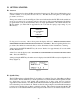
APPENDIX A - Cone/Plate Rheometer Set-Up The Cone/Plate (C/P) version of the DV-III Rheometer uses the same operating instruction procedures as described in this manual. However, the gap between the cone and the plate must be mechanically adjusted before measurements are made. This is done by moving the plate (built into the sample cup, Part No. CP-44Y) up towards the cone until two small pins (one in the cone, the second mounted on the plate) contact slightly, and then by separating (lowering) the plate 0.
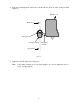
Remove sample cup and attach the cone to the Rheometer (Note: left hand threads), using the spindle wrench to hold the Rheometer shaft (Figure A2). Note: Lift up gently on the spindle wrench. These Surfaces These surfaes Mustmust be Clean! be clean!!! Spindle Wrench Spindle Wrench Cone Cone Figure A2 Attach the sample cup and swing the clip under the cup to secure it in place. Take care to avoid hitting the cone with the cup (Figure A3). Note: Do not add test sample during the gap setting procedure.
Index Mark Index Mark Adjusting Ring Adjustment Ring Turn Adjustment Ring Clockwise Until the % Torque Display is Stable at 0.0% Turn Adjusting Ring clockwise until the % torque display is stable at 0.0% Figure A4 Turn the adjustment ring to the right (counterclockwise as you look down on the instrument) in small increments (one or two divisions of the ring) while watching the Rheometer % display (Figure A5).
When you are satisfied the pins are just hitting (by observing acceptable % readings), make a pencil mark on the adjustment ring directly under the index mark on the pivot housing (Figure A6).
Each of the five available cones has a specific sample volume, as shown in Table A1. Note that the correct amount of sample fluid should cover the cone face and back up over the edge less than 1mm as shown in (Figure A8). Less Lessthan Than 1 1mm mm Cone Cone Sample Sample Cup Cup Figure A8 Notes: a) The cup may be removed without resetting the gap. b) Remove the spindle from the Rheometer when you clean it. c) Reset the hit point every time the spindle is attached.
It is best to use a viscosity standard fluid that will be close to the maximum viscosity for a given cone spindle/speed combination. Example: LVDV-III Rheometer, Cone CP-42, Fluid 10 Having a viscosity of 9.7 cP at 25°C At 60 RPM, the full scale viscosity range is 10.0 cP. Thus, the Rheometer reading should be 97% torque and 9.7 cP viscosity ± 0.197 (0.1 cP for the viscometer plus 0.97 cP for the fluid).
APPENDIX B - Viscosity Ranges The table below (Universal Spindle Ranges) lists the Spindle Range Coefficients for all spindles used on DV-III Rheometers. Dividing the coefficient number by any of the 2,500 Rheometer speeds will give the full scale viscosity range for a Rheometer/spindle/speed combination.
Universal Spindle Ranges Spindle Range Coefficient Spindle Entry Code Rheometer Series LV RV HA HB DIN-81 DIN-82 DIN-83 DIN-85 DIN-86 DIN-87 81 82 83 85 86 87 3,420 3,420 11,340 1,144 3,420 11,340 36,500 36,500 121,300 12,200 36,500 121,300 73,000 73,000 242,600 24,400 73,000 242,600 292,000 292,000 970,400 97,600 292,000 970,400 SC4-14 SC4-15 SC4-16 SC4-18 SC4-21 SC4-25 SC4-27 SC4-28 SC4-29 SC4-31 SC4-34 SC4-37 14 15 16 18 21 25 27 28 29 31 34 37 117,200 46,880 120,000 3,000 4,688 480,000 23,
Example 1: Determine the full scale viscosity range of the LV3 spindle running on an RV series Rheometer at 45 RPM. Spindle Speed = 45 RPM LV3 Spindle Range Coefficient for RV series Rheometer = 1,280,000 Full Scale Viscosity Range = 1,280,000 = 28,444 cP (mPa•s) 45 Example 2: Determine the full scale viscosity range of the LV3 spindle running on a 2xHA Rheometer at 103.5 RPM. Spindle Speed = 103.
Thermosel Viscosity (cP) Shear Spindle Rate (s-1) 18 21 27 28 29 31 34 81 0 0 0 0 0 0 0 0 - 264 - 186 - 68 - 56 - 50 - 68 - 56 - 258 LV cP 1.3 1.9 9.4 18.8 37.5 12.0 24.0 1.4 - RV cP 30,000 46,865 234,325 468,650 937,300 300,000 600,000 10,000 12.8 20.0 100.0 200.0 400.0 128.0 256.0 15.0 HA cP 320,000 500,000 - 2,500,000 - 5,000,000 - 10,000,000 - 3,200,000 - 6,400,000 10,000 25.6 40.0 200.0 400.0 800.0 256.0 512.0 30.
Helipath with T-Bar Spindles Viscosity (cP) T-Bar Spindle LVDV-III RVDV-III HADV-III T-A 156 - 187,460 2,000 - 2,000,000 4,000 - 4,000,000 T-B 312 - 374,920 4,000 - 4,000,000 8,000 - 8,000,000 T-C 780 - 937,300 10,000 - 10,000,000 20,000 - 20,000,000 T-D 1,560 - 1,874,600 20,000 - 20,000,000 40,000 - 40,000,000 T-E 3,900 - 4,686,500 50,000 - 50,000,000 100,000 - 100,000,000 T-F 7,800 - 9,373,000 100,000 - 100,000,000 200,000 - 200,000,000 HBDV-III 16,000 - 16,000,000 32,000 - 32,000,000 80,000 - 80,000,000
APPENDIX C - Variables in Viscosity Measurements As with any instrument, there are variables that can affect a viscosity measurement. These variables may be related to the instrument (Rheometer) or the test fluid. Variables related to the test fluid deal with the rheological properties of the fluid, while instrument variables would include the Rheometer design and the spindle geometry system utilized.
A repeatable viscosity test should control or specify the following: 1) 2) 3) 4) 5) 6) 7) Test temperature Sample container size (or spindle/chamber geometry) Sample volume Rheometer model Spindle used (if using LVDV-III(#1-4) or RVDV-III(#1-7) attach the guard leg) Test speed or speeds (or the shear rate) Length of time or number of spindle revolutions to record viscosity.
APPENDIX D - Spindle and Model Codes Each spindle has a two digit code which is entered using the SPDL key on the DV-III key pad. The entry code allows the DV-III to calculate Viscosity, Shear Rate and Shear Stress values. Each spindle has two constants which are used in these calculations. The Spindle Multiplier Constant (SMC) used for viscosity calculations, and the Shear Rate Constant (SRC), used for shear rate and shear stress calculations.
Table D1 (continued) SPINDLE ENTRY CODE SC4-27 SC4-28 SC4-29 SC4-31 SC4-34 SC4-37 CP40 CP41 CP42 CP51 CP52 Spiral Adapter Thermosel DIN spindle SSA DIN spindle for 13R or 13RP chamber SSA DIN spindle for 7R or 7RP chamber ULA DIN spindle ULA DIN spindle ULA DIN spindle SMC SRC 27 28 29 31 34 37 40 41 42 51 52 70 81 25 50 100 32 64 25 0.327 1.228 0.64 5.12 9.83 105 3.7 0.34 0.28 0.25 0.34 0.28 0.36 7.5 2 3.8 3.84 2 0.677 1.29 82 3.75 1.29 83 85 86 87 12.09 1.22 3.65 12.13 1.29 1.29 1.29 1.
The Shear Rate calculation is: Shear Rate (1/Sec) = SRC * RPM Where: SRC = Shear Rate Constant from Table D1 Using Non-standard spindles with DV-III Spindle Entry 99 allows entry of spindle constants which the DV-III will use to calculate Viscosity, Shear Rate and Shear Stress for spindles in boundary conditions other than the 600ml beaker or specified chamber. The spindles must conform to geometries that allow for mathematical calculations of Shear Rate and Shear Stress i.e. coaxial cylinder.
Shear Rate (1/sec) = 2ω Rc2 Rb2 χ 2 [Rc2 – Rb2] Where: Rc = Radius of the container (in centimeters) Rb = Radius of the spindle (in centimeters) χ = Radius at which the shear rate is to be calculated (normally the same value as Rb; in centimeters) ω = Angular velocity of the spindle (Rad/Sec) ω= 2π 60 * N N = Spindle speed in RPM The procedure for entering SMC and SRC values is: 1) From the main screen, press SELECT SPDL.
APPENDIX E - Calibration Procedures The accuracy of the DV-III is verified using viscosity standard fluids which are available from Brookfield Engineering Laboratories or your local Brookfield agent. Viscosity standards are Newtonian, and therefore, have the same viscosity regardless of spindle speed (or shear rate). Viscosity standards, calibrated at 25°C, are shown in Table E1. Container size: For Viscosity Standards < 30,000 cP, use a 600 ml Low Form Griffin Beaker having a working volume of 500 ml.
for usage in a 600 ml beaker is to return the material from the beaker back into the bottle. When using smaller volumes in accessories such as Small Sample Adapter, UL Adapter or Thermosel, the fluid is normally discarded. Calibration Procedure for LV(#1-4) and RV,HA,HB(#1-7) Brookfield spindles: 1) Place the viscosity standard fluid (in the proper container) into the water bath. 2) Lower the DV-III into measurement position (with guard leg if LV or RV series Rheometer is used).
A) Evaluate the calibration of the Viscometer alone according to the procedure outlined in Appendix E, “Calibration Procedure for LV (#1-4) and RV,HA,HB (#1-7) Brookfield spindles.” B) Evaluate the Viscometer with Thermosel according to the procedure listed below: a) Put the proper amount of HT viscosity standard fluid into the HT-2 sample chamber. The amount varies with the spindle used. (Refer to the Thermosel instruction manual). b) Place the sample chamber into the Thermo Container.
3) Lower the DV-III into measurement position. Operate the viscometer at 50 or 60 RPM until the chamber is fully flooded. 4) The viscosity standard fluid, together with the spindle, should be immersed in the bath for a minimum of 1 hour, stirring the fluid periodically (operate at 50 or 60 RPM periodically), prior to taking measurements. 5) After 1 hour, check the temperature of the viscosity standard fluid with an accurate thermometer. 6) If the fluid is at test temperature (+/- 0.
3) Select a viscosity standard fluid that will give viscosity readings between 10% and 00% of full scale range. Refer to Appendix B for viscosity ranges of cone spindles. Do not use a silicone viscosity standard fluid with a viscosity value greater than 5000 cP with a Cone/Plate Viscometer. Brookfield offers a complete range of mineral oil viscosity standards suitable for use with Cone/Plate Viscometers as shown in Table E2.
3) Total allowable error is (122.57 + 500) cP = (+/-) 622.57 cP. 4) Therefore, any viscosity reading between 11,634.4 and 12,879.6 cP indicates that the Rheometer is operating correctly. Any reading outside these limits may indicate a Rheometer problem. Contact the Brookfield technical sales department or your local Brookfield dealer/distributor with test results to determine the nature of the problem. The Brookfield Guardleg The guard leg was originally designed to protect the spindle during use.
Section 3.3.10. It is important to note that for many viscometer users the true viscosity is not as important as a repeatable day to day value. This repeatable value can be obtained without any special effort for any measurement circumstance. But, it should be known that this type of torque reading will not convert into a correct centipoise value when using a Brookfield factor if the boundary conditions are not those specified by Brookfield.
APPENDIX F - VS-27Y Clamp Assembly The VS-27Y Clamp assembly holds the DV-III on the upright rod and thus supports it on the base. The parts are shown in Figure F1. VS-26Y Clamp Screw Assembly VS-29 Tension Insert VS-29W Washers VS-28 Tension Screw Figure F1 If the clamp is taken off the upright rod, the tension insert (Part No. VS-29) must be properly aligned for the clamp to fit back onto the upright rod. When the tension insert (Part No.
APPENDIX G - Communications The command set used to communicate with the DV-III is as follows: COMMAND Name COMMAND from Computer RESPONSE from DV-III k(Reset) E(nable) R(etrieve) V(elocity) I(dentify) Z(ero) Illegal String No Response Where: vvvv = Transducer reading as 4 hex digits.
The status byte is decoded as follows: Figure G1 Note: These values are not updated in the status byte when the listed condition occurs. They are made available when the computer next requests transducer readings or attempts a motor command. The flags are cleared by re-enabling the DV-III. The I(dentify) command is optional and will cause the DV-III to respond with the ASCII string “DV3”. This command is used as a means of identifying Brookfield instruments connected to a computer serial ports.
appending the status byte which will, amongst other things, inform the calling program as to whether the motor was turned on and/or whether the desired speed was attained. The Z(ero) command is used to “zero” the DV-III Rheometer. The value returned is usually in the range of 03F0 hex to 0400 hex. This number should be retained and subtracted from every future returned torque reading to obtain the actual Rheometer torque in percent.
A sample program demonstrating the above principles is contained in the following listing. Please note that this is an example only and does not include advanced programming techniques or error trapping.
1265 1270 1275 1280 1285 1290 1295 1300 1305 1310 1315 1320 1325 1330 1335 1340 1345 1350 1355 1360 1365 1370 1375 1380 1385 1390 1395 1400 1405 1410 1415 1420 1425 1430 1435 1440 1445 1450 1455 1460 1465 1470 1475 1480 1485 1490 1495 1500 1505 1510 1515 1520 1525 1530 1535 1540 1545 PRINT SPC C(3); DV3COMMAND$ = “V” + HEXRPM$ G O S U B 1815 G O S U B 1870 G O S U B 1540 DV3COMMAND$ = “R” G O S U B 1815 G O S U B 1870 G O S U B 1920 P R I N T “%=”; P R I N T U S I N G “###.
1550 1555 1560 1565 1570 1575 1580 1585 1590 W H I L E (T2 - T1) < TINTERVAL T2 = T I M E R WEND RETURN 1595 1600 1605 1610 1615 1620 1625 1630 1635 1640 1645 1650 1655 1660 1665 1670 1675 1680 1685 1690 1695 1700 1705 1710 1715 1720 1725 1730 1735 1740 1745 1750 1755 1760 1765 1770 1775 1780 1785 1790 1795 1800 1805 1810 1815 1820 1825 1830 TEMPRPM = RPM * 10 HEXRPM$ = H E X $ $(TEMPRPM) ISFOUR = 4 - L E N N(HEXRPM$) W H I L E ISFOUR > 0 HEXRPM$ = “0” + HEXRPM$ ISFOUR = ISFOUR - 1 WEND RETURN ‘ Loop un
1835 1840 1845 1850 1855 1860 1865 1870 1875 1880 1885 1890 1895 1900 1905 1910 1915 1920 1925 1930 1935 1940 1945 1950 1955 1960 1965 1970 1975 1980 1985 1990 1995 2000 2005 2010 2015 2020 2025 2030 2035 2040 2045 2050 2055 2060 2065 2070 2075 2080 2085 G O S U B 1455 N E X T CMD RETURN ‘ Delay between characters ‘ ‘+ +——————————————————————————+ ‘| | Routine to receive a response from the DV-III ‘+ +——————————————————————————+ | RESP$ = “” W H I L E RIGHT$(RESP$,1) <> CR$ ‘ Wait for a carriage retur
Brookfield Engineering Labs DV-III External Mode Demonstration Program Copyright 1991 This program is intended to demonstrate the use of the RS-232 command set employed by the Brookfield Engineering Labs Model DV-III Rheometer in its External mode. This program and/or any of the commands used within may be freely used in your own applications. Press any key to continue... Please remove the spindle and press any key to begin the Auto-Zero process. Auto-Zeroing... Auto-Zero complete.
Output Connections The DV-III has two analog voltage outputs available for strip chart recording and one RS232 output for computer or serial printer. The analog voltages are: 0 - 1 volt DC corresponding to 0 to 100 Torque % 0 - 4 volts DC corresponding to -100 °C to +300 °C at 10 millivolts per °C The location of the connector is shown in Figure G2: Connector RS-232 Serial Printer/Computer Analog Output(s) APPROVED POWER SUPPLY TUV RHEINLAND LICENSE NO. R9051346 RECOGNIZED COMPONENT UL FILE NO.
When connecting the DV-III to a serial printer, use Brookfield Printer Cable (Part No. DVP-81). The cable connections are: Printer RxD (usually pin 3) to DV-III TxD (pin 3) Printer Txd (usually pin 2) to DV-III RxD (pin 2) Printer ground (pin 7) to DV-III serial ground (pin 5) When connecting a computer to the DV-III, use Brookfield Computer Cable (Part No. DVP-80).
APPENDIX H - DVE-50 Probe Clip Probe Clip DVE-50 is supplied with all model DV-III Rheometers and Digital Temperature Indicators. It is used to attach the RTD temperature probe to the LV Guard Leg (Part No. B20Y) or 600 ml low form Griffin beaker. Figure H1 is a view of the Probe Clip, showing the hole into which the RTD probe is inserted, and the slot which fits onto the LV guard leg.
APPENDIX I - Fault Diagnosis and Troubleshooting A diagnostics option (Option 5) was supplied on DV-III Rheometers with firmware versions up to 2.0. It checks all DV-III electronic components: circuit boards, serial interface, motor control, display and keyboard. This option is used when a malfunction is suspected. Pressing the number 5 key from the Options screen begins the test sequence with instructions provided on the screen. On DV-III Rheometers with Version 3.
2. Spindle jammed below zero • Contact Brookfield Engineering Laboratories, Inc. or your Brookfield dealer for repair Display Reading Over 100 1. Overrange “EEE” (in %, cP, and SS) • Change spindle and/or speed Rheometer Will Not Return to Zero 1. Pivot point or jewel bearing faulty • Perform calibration check, Section 3.3.9 of "More Solutions to Sticky Problems" • Contact Brookfield Engineering Laboratories, Inc. or your Brookfield dealer for repair Display Reading Will Not Stabilize 1.
Appendix J - Warranty Repair and Service Warranty Brookfield Viscometers are guaranteed for one year from date of purchase against defects in materials and workmanship. They are certified against primary viscosity standards traceable to the National Institute of Standards and Technology (NIST). The Viscometer must be returned to Brookfield Engineering Laboratories, Inc. or the Brookfield dealer from whom it was purchased for no charge warranty service. Transportation is at the purchaser’s expense.